Theme: Accuracy specifications
The overall accuracy of a process measurement never gets better than the weakest link in the chain. It is therefore important to evaluate all relevant aspects regarding accuracy before choosing a signal amplifier.
Data terms
At PR electronics we use the term FS. FS means "full span" value, that is current measured value. Thus the full span value of a temperature transmitter with the measurement range 0...250°C is 250°C.
Example:
Linearity error = ±0.25% FS (0...250°C).
| Current measurement |
Absolute deviation |
%-error of actual measurement |
| 10°C | ±0.625°C | ±6.2% |
| 50°C | ±0.625°C | ±1.2% |
| 100°C | ±0.625°C | ±0.62% |
| 150°C | ±0.625°C | ±0.40% |
| 200°C | ±0.625°C | ±0.30% |
| 250°C | ±0.625°C |
±0.25% |
The calculations show that it is most favorable to choose a measurement range so that the normal measured value is between 50 and 100% of the full span value.
What can affect electronic circuits?
Both external and internal factors affect an electronic circuit.
Examples of external factors: Load, HF noise, ambient temperature, fluctuations in voltage supply or induction noise.
Examples of internal factors: Nonlinear components, selfheating or internal noise (rippel).
It is the mechanical and electronic design that determines how effectively these various factors are suppressed.
All mentioned factors contribute to the accuracy of the signal amplifier and should therefore be included in a calculation. Below, however, we will focus on a small segment, which must be considered some of the worst culprits.
Temperature coefficient:
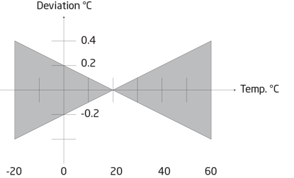
All electronic equipment is influenced by changes in the ambient temperature. On delivery, the signal amplifier is calibrated at room temperature (+20°C). The more the ambient temperature deviates from +20°C, the larger error. The temperature coefficient is stated as e.g. ±0,01% FS/°C.
 |
| The measurement accuracy changes when the ambient temperature varies from the temperature at which the signal amplifier was factory calibrated. |
Linearity error:
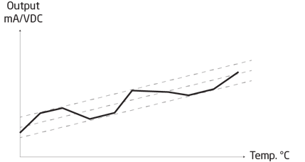
Is stated as e.g. ±0,1% FS. This is the max. margin of error the transmitter has from the ideal curve.
 |
| The linearity error is the max. limits within which the current error is allowed to oscillate. The error is increasing when measuring in higher temperature ranges. |
Adjustment accuracy:
This is a factor which is rarely described in data sheets. In our standard specifications at PR electronics we have defined the requirement as <±0,1% FS. Based on the accuracy requirements of the product, the requirements of our test and calibration equipment for measuring DC voltage and current are a factor 7 better. In order to ensure that the above factor is complied with during final testing and adjustment of our products the measuring equipment is calibrated according to a fixed plan by external accredited laboratories.
Typical and "worst case" accuracies:
When an accuracy is tested, it is usually only the parameter that is to be tested that is changed. All other parameters are kept constant in order to obtain a clear picture of the impact of the parameter.
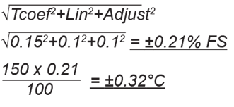
Accuracies may differ in a positive or negative direction compared to the ideal value. This means that the deviation can be larger or smaller than the absolute right. Therefore, it is often relevant to calculate a typical deviation as some deviations are positive and some negative and therefore offsets each other. A typical deviation is therefore calculated as the sum of squares of the separate accuracies.

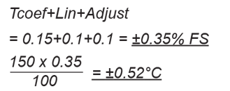
Worst case indicates the sum of deviations, where it is theoretically assumed that all errors move in the same direction by which the largest possible error occurs.

Calculation of total overall accuracy:
Measurement task:
| Temperature transmitter | Pt100 Ω |
| Temperature range | 0...150°C |
| Ambient temperature, Tamb. | 35°C |
|
Accuracy of the transmitter |
|
| Linearity | <±0.1% FS |
| Temperature coefficient | <±0.01% FS |
| Adjustment accuracy | <±0.1% FS |
| Temperature coefficient | <±0.01% FS/°C (factory-calibrated at 20°C) |
| Ambient temperature, Tamb. | = 35°C |
| Temperature coefficient = | 0.01 x (35-20) = ±0.15% FS |
Typical accuracy (according to formula):

Worst case accuracy (according to formula):

If you want to compare the accuracy specifications of two products, it's important to convert to identical terms in order to form a reliable frame of reference.
The process of manufacturing chloroacetic acid is divided into several process steps. Each step is complicated requiring high temperature measuring accuracy for the control system – as well as intrinsically safe devices.
Problems with transmitters not providing accurate signals – or no output signals
Prior to testing PR temperature transmitters, the plant had experienced problems with temperature transmitters not providing accurate signals or, for unknown reasons, failing to provide output signals. Temperature is a vital parameter in chemical processes. When failing, it can lead to process stop and affect the entire plant performance.


