


Programmable transmitter
5114A
- Input for RTD, TC, mV, linear resistance, mA, and V
- 3-port 3.75 kVAC galvanic isolation
- Current and voltage output
- Universal voltage supply
- 1- and 2-channel versions
- Loop supply > 17.1 V
Advanced features
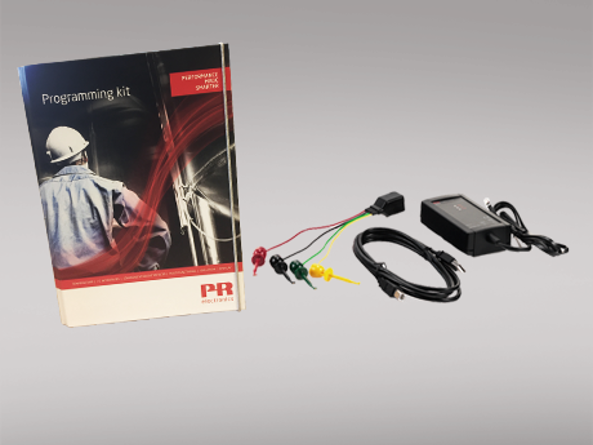
- The 5114 transmitter can be configured using the PReset software and the Loop Link communications unit.
Application
- Jumper selectable inputs for current/voltage or temperature.
- Programmable current (0...100 mA) and voltage (0...250 VDC) inputs.
- Linearized, electronic temperature measurement.
- Conversion of linear resistance variation e.g, from solenoids and butterfly valves or linear movements with attached potentiometer.
- 17.1 VDC loop and 2.5 VDC potentiometer supplies.
- Automatic 4- / 3-wire or programmable 2-wire cable compensation.
- Configurable sensor error detection including NAMUR NE43.
Technical characteristics
- Active or Passive current output and selectable voltage output.
- Separation of circuits in PELV/SELV installations.
Scheda tecnica & manuali
Scheda tecnica
- 5114A.pdf
- Ultima versione
Manuali
- 5114V108_UK.pdf
- 5114V107_UK.pdf
- 5114V106_UK.pdf
- 5114V105.pdf
- Versione precedente
- Ultima versione
Manuali in russo
- 5114V108_RU.pdf
- 5114V107_RU.pdf
- 5114L106_RU.pdf
- Versione precedente
- Ultima versione
Documentazione supplementare
Dichiarazione UE di conformità
- 5114DoC_EU_103_UK.pdf
- 5114DoC_EU_102_UK.pdf
- 5114DoC_EU_101_UK.pdf
- 5114DoC_EU_100_UK.pdf
- Versione precedente
- Ultima versione
Configurazioni predefinite
- PR_default_configurations.pdf
- Ultima versione
Note di sicurezza
Note di sicurezza
- SN5000-2-109-2220.pdf
- SN5000-2-107-1924.pdf
- SN5000-2-106-1825.pdf
- SN5000-2-105-1811.pdf
- SN5000-2-104-1725.pdf
- SN5000-2-103-1625.pdf
- SN5000-2-102-1613.pdf
- SN5000-101-1450.pdf
- Versione precedente
- Ultima versione
Approvazioni & certificati
Certificato marina DNV
- DNV_2231_41xx_51xx_53xx.pdf
- Ultima versione
Dichiarazione EAC
- EAC-Declaration.pdf
- Ultima versione
Dichiarazione LVD EAC
- EAC_LVD-Declaration.pdf
- Ultima versione
Metrology Pattern Approval (MPA), Russia
Modulo di ordine
Environmental Conditions
| Operating temperature | -20°C to +60°C |
| Calibration temperature | 20...28°C |
| Relative humidity | < 95% RH (non-cond.) |
| Protection degree | IP20 |
Mechanical specifications
| Dimensions (HxWxD) | 109 x 23.5 x 130 mm |
| Weight approx. | 225 g |
| DIN rail type | DIN EN 60715/35 mm |
| Wire size | 0.13...2.08 mm2 AWG 26...14 stranded wire |
| Screw terminal torque | 0.5 Nm |
Common specifications
Supply |
|
| Supply voltage, universal | 21.6...253 VAC, 50...60 Hz or 19.2...300 VDC |
| Fuse | 400 mA SB / 250 VAC |
| Max. required power | 2.1 W / 2.8 W (1 / 2 ch.) |
| Max. power dissipation | 2.0 W |
Isolation voltage |
|
| Isolation voltage, test / working | 3.75 kVAC / 250 VAC |
| PELV/SELV | IEC 61140 |
Response time |
|
| Temperature input, programmable (0...90%, 100...10%) | 400 ms...60 s |
| mA / V input (programmable) | 250 ms...60 s |
Auxiliary supplies |
|
| 2-wire supply (pin 44...42 and 54...52) | 28...17.1 VDC / 0...20 mA |
| Programming | Loop Link |
| Signal / noise ratio | Min. 60 dB (0...100 kHz) |
| Accuracy | Better than 0.05% of selected range |
| Updating time |
115 ms (temperature input)
75 ms (mA / V / mV input) |
| Signal dynamics, input | 22 bit |
| Signal dynamics, output | 16 bit |
| Auxiliary voltages: Reference voltage | 2.5 VDC ±0.5% / 15 mA |
| EMC immunity influence | < ±0.5% of span |
| Extended EMC immunity: NAMUR NE21, A criterion, burst | < ±1% of span |
Input specifications
Common input specifications |
|
| Max. offset | 50% of selected max. value |
RTD input |
|
| RTD type | Pt100, Ni100, lin. R |
| Cable resistance per wire | 10 Ω (max.) |
| Sensor current | Nom. 0.2 mA |
| Effect of sensor cable resistance (3-/4-wire) | < 0.002 Ω / Ω |
| Sensor error detection | Yes |
TC input |
|
| Thermocouple type | B, E, J, K, L, N, R, S, T, U, W3, W5, LR |
| Cold junction compensation (CJC) | < ±1.0°C |
| Sensor error current | Nom. 30 μA |
| Sensor error detection | Yes |
Current input |
|
| Measurement range | 0...100 mA |
| Min. measurement range (span) | 4 mA |
| Input resistance: Supplied unit | Nom. 10 Ω + PTC 10 Ω |
| Input resistance: Non-supplied unit | RSHUNT = ∞, VDROP < 6 V |
Voltage input |
|
| Measurement range |
0...250 VDC
-150...+150 mV |
| Min. measurement range (span) | 5 mV |
| Input resistance |
Nom. 10 MΩ (≤ 2.5 VDC)
Nom. 5 MΩ (> 2.5 VDC) Nom. 10 MΩ (mV input) |
Output specifications
Current output |
|
| Signal range | 0...20 mA |
| Min. signal range | 10 mA |
| Load (@ current output) | ≤ 600 Ω |
| Load stability | ≤ 0.01% of span / 100 Ω |
| Current limit | ≤ 28 mA |
| Sensor error indication | Programmable 0...23 mA |
| NAMUR NE43 Upscale/Downscale | 23 mA / 3.5 mA |
Passive 2-wire mA output |
|
| Signal range | 4...20 mA |
| Load stability | ≤ 0.01% of span / 100 Ω |
| Max. external 2-wire supply | 29 VDC |
| Effect of external 2-wire supply voltage variation | < 0.005% of span / V |
Voltage output |
|
| Signal range | 0...10 VDC |
| Min. signal range | 500 mV |
| Load (@ voltage output) | ≥ 500 kΩ |
| of span | = of the presently selected range |
Observed authority requirements
| EMC | 2014/30/EU |
| LVD | 2014/35/EU |
| RoHS | 2011/65/EU |
| EAC | TR-CU 020/2011 |
| EAC LVD | TR-CU 004/2011 |
Approvals
| DNV Marine | TAA0000101 |


Need support to select the right product for your application?
Our sales engineers are ready to help specify the right device to meet your needs.
Reach out by phone to get in touch with us straight away – or use the contact form or quick quote function to send your RFQ directly from the website. You’ll get a response within 24 hours on normal business days.
You can expect to get a confirmed delivery date via email within 2 days after we have received your order.
As soon as your package leaves our warehouse, you’ll receive tracking details via email. And if you have any questions along the way we’re just a phone call or email away.
 |
State-of-the-art manufacturing Our 8,500 sqm integrated and automated manufacturing campus in Denmark covers the entire value-chain from design and development to manufacturing. It allows us to design and optimize for testing and manufacturing thereby constantly driving quality up and costs down. |
 |
Dedicated Presale / Aftersales
|
 |
Product reliability |
 |
Product deployment
|
 |
Smart products
Check out our range of communication interfaces
|
