


Universal trip amplifier
PR 4179B
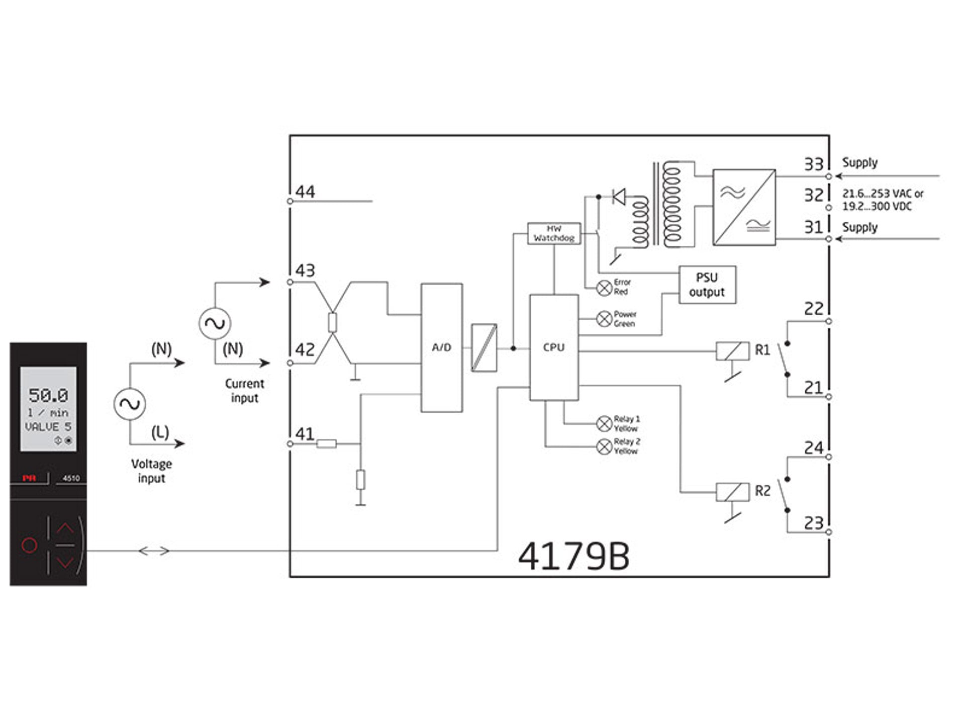
- Measures AC current and voltage signals
- Output: 2 relays
- Programming, process monitoring and diagnostics via PR 4500
- Universal power supply 21.6…253 VAC / 19.2...300 VDC


Functional highlights
- The 0... 5 AAC RMS range makes it possible to accurately measure a typical current transformer.
- The 0...300 VAC RMS range allows accurate supply voltage monitoring.
- The device measures standard input ranges and can be freely configured to customer-defined input range.
- Process control with 2 pairs of potential-free relay contacts which can be configured to suit any application.
- Trip amplifier with window function allowing the relay to change state within a high and a low setpoint on the input span.
- Simulation of process value during commissioning / maintenance.
- All terminals are over-voltage protected, polarity protected and short-circuit protected.
- The 4179B provides the required failure data (SFF and PFDAVG) for SIL 2 applications as per IEC 61508 / IEC 61511.
- Failure rates for 4179B correspond to Performance Level “d” according to ISO-13849.
Technical characteristics
- Accuracy < 0.3% of span.
- Temperature coefficient 0.01% / °C.
- Response time < 0.75 s for measuring AC current / voltage signals.
- High galvanic isolation of 2.3 kVAC.
- Extended EMC immunity: NAMUR NE21, A criterion, burst.
- Functional safety: HW assessment, SFF > 90%.
Programming
- Configuration, monitoring and diagnostics using PR 4500 detachable communication interfaces. Product-specific functionality includes communication via Modbus and Bluetooth using our PR Process Supervisor (PPS) application, available for iOS and Android.
- All programming can be password protected.
- Scrolling help text in 7 languages.
Mounting / installation
- Units can be mounted side by side, horizontally and vertically, without air gap on a standard DIN rail, even at 60°C ambient temperature.
Note
- If you need an installation instruction in hard copy, you can order it for free when placing your order.
Data sheet & Manuals
Supplementary documentation
EU Declaration of Conformity
- 4179BDoC_100_UK.pdf
- Latest version
UKCA Declaration of Conformity
- 4179BDoC_UKCA_100_UK.pdf
- Latest version
Modbus configuration manual
- 4179B_MCM_100.pdf
- Latest version
FMEDA report
- PR_4179B_V1R3.pdf
- Latest version
EAC LVD declaration
- 4179B_EMC_data.pdf
- Latest version
PR default configurations
- PR_default_configurations.pdf
- Latest version
China RoHS
- China_RoHS.pdf
- Latest version
Approvals & Certificates
View variants
Environmental Conditions
| Operating temperature | -20°C to +60°C |
| Storage temperature | -20°C to +85°C |
| Calibration temperature | 20...28°C |
| Relative humidity | < 95% RH (non-cond.) |
| Protection degree | IP20 |
| Installation in | Pollution degree 2 & meas. / overvoltage cat. II |
Mechanical specifications
| Dimensions (HxWxD) | 109 x 23.5 x 104 mm |
| Dimensions (HxWxD) w/ PR 4500 | 109 x 23.5 x 131 mm |
| Weight approx. | 155 g |
| DIN rail type | DIN EN 60715/35 mm |
| Wire size | 0.13...2.08 mm2 AWG 26...14 stranded wire |
| Screw terminal torque | 0.5 Nm |
| Vibration | IEC 60068-2-6 |
| 2...13.2 Hz | ±1 mm |
| 13.2...100 Hz | ±0.7 g |
Common specifications
Supply |
|
| Supply voltage, universal | 21.6...253 VAC, 50...60 Hz or 19.2...300 VDC |
| Internal fusible resistor | < 80 s, 2.4 A |
| Max. required power | 1.2 W (1) |
| Max. power dissipation - current measurement | 2.2 W |
| Max. power dissipation - voltage measurement | 1.2 W |
Isolation voltage |
|
| Test voltage | 2.3 kVAC |
| Input to any (working) | 250 VAC (reinforced) |
| Relay to relay (working) | 125 VAC (reinforced) |
Response time |
|
| Response time (0...90%, 100...10%) | < 0.75 s |
| Signal dynamics, input | 20 bit |
| Bandwidth | 40…400 Hz |
| Programming | PR 4500 communication interfaces |
| EMC immunity influence | < ±0.5% of span* |
| Extended EMC immunity: NAMUR NE21, A criterion, burst | < ±1% of span* |
| of span | = of selected standard range |
Input specifications
Current input |
|
| Signal range | 0...5 AAC / 40...400 Hz |
| Maximum input limit | 6.00 AAC @ 40°C |
| Programmable measurement ranges | 0...0.5; 0…1; 0…2.5 & 0...5 AAC |
| Custom configurable signal range | 0...5 AAC /40...400 Hz |
| Min. measurement range (span) | 0.5 AAC |
| Input resistance | < 0.042 Ω (incl. terminals) |
Voltage input |
|
| Signal range | 0...300 VAC / 40...400 Hz |
| Programmable measurement ranges | 0...0.5, 0...1, 0...2.83, 0…5, 0…120, 0…230 & 0…300 VAC |
| Custom configurable signal range | 0...300 VAC / 40...400 Hz |
| Min. measurement range (span) | 0.5 VAC |
| Input resistance | Nom. 3 MΩ || 100 pF |
Output specifications
Relay output |
|
| Relay functions | Setpoint, Window, Error indication, Latch, Power and Off |
| Hysteresis | 0...100% |
| ON and OFF delay | 0...3600 s |
| Power On delay | 0...9999 s |
| Max. voltage | 250 VAC / VDC |
| Max. current | 2 A |
| Max. AC power | 500 VA |
| Max. DC current, resistive load ≤ 30 VDC (1) | 2 ADC |
| Max. DC current, resistive load > 30 VDC | See manual for details |
Observed authority requirements
| EMC | 2014/30/EU & UK SI 2016/1091 |
| LVD | 2014/35/EU & UK SI 2016/1101 |
| RoHS | 2011/65/EU & UK SI 2012/3032 |
Approvals
| c UL us, UL 508 | E248256 |
| SIL | Hardware assessed for use in SIL applications |