Difference between a Zener barrier and an intrinsically safe isolator
Often referred to as ATEX barriers, intrinsically safe barriers or I.S. barriers, both Zener barriers and intrinsically safe galvanic isolators restrict the energy to the hazardous area. However, there are distinct differences in the design of each type of device.
How does a Zener barrier work?
The operating principle of a Zener barrier is relatively simple. Understanding the difference between a diode and a Zener diode is key: while a regular diode allows current to flow in only one direction, a Zener diode is designed to conduct in reverse once a specific voltage threshold is reached—essentially answering how does Zener diode work in this application. Resistors restrict the current entering the hazardous area, and in a fault condition, the Zener diodes clamp the voltage and divert excess current to earth. A fuse is present to protect the Zener diodes in the event of an overload condition.
What is a Zener barrier?
Zener barriers are simple devices made up of an arrangement of Zener diodes, resistors and fuses that limit the voltage, current, and power to connected devices in the hazardous area.
A typical Zener barrier installation is shown below.
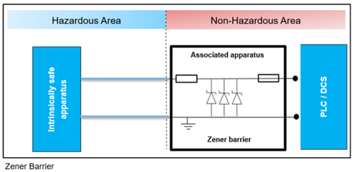
The operating principle of a Zener barrier is relatively simple. Resistors restrict the current entering the hazardous area, whilst Zener diodes conduct in the event of a fault condition clamping the voltage and diverting excess current to earth. A fuse is present to protect the Zener diodes in the event of an overload condition.
Understand the differences between Isolated barriers vs. Zener barriers.
For correct functionality and to maintain intrinsic safety, a dedicated I.S. ground is required, which must be installed and maintained in accordance with IEC 60079-14.
This requirement, together with more restrictive loop loading and functional limitations mean Zener barriers have been largely superseded by intrinsically safe galvanic isolators.
What is an intrinsically safe galvanic isolator?
The design of intrinsically safe galvanic isolators such as the PR 9000 series of devices differs from Zener barriers.
Both devices restrict the energy available to the hazardous area, but by using components such as transformers and opto-isolators in the design it is possible to achieve galvanic isolation between the input, output and supply. This is known as 3-port galvanic isolation as shown in the graphic below.
Loop powered and 2-port galvanic isolators are also available depending on application.
A typical intrinsically safe 3-port galvanic isolator installation is shown below.
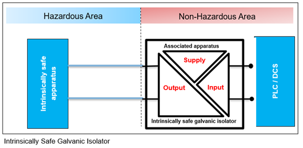
As these devices incorporate galvanic isolation, a dedicated I.S. ground is not required. This alone simplifies installation and ongoing maintenance compared to Zener barriers.
Other advantages of intrinsically safe galvanic isolators include:
- Lower loop loading
- Ability to convert and amplify signals
- Improved noise and surge immunity
For further information on the differences between Zener barriers and intrinsically safe galvanic isolators, see Isolated barriers vs Zener barriers.
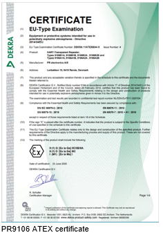
What is Hazardous Area Certified Equipment?
Equipment for installation in hazardous areas or associated apparatus must be safe for intended use and be compliant with any explosion protection method employed.
Within the EU, such equipment must be ATEX certified.
Whilst ATEX certification is required in Europe, there is also the IECEx certification which is recognized internationally across various countries.
Although IECEx is widely accepted, some country specific certifications may be required.
Certifications should be conducted by a notified body and will demonstrate compliance with the relevant standards and protection methods.
Certificates contain important information relating to the product, including:
|
 |
To ensure safety, hazardous area certified equipment must be installed as per relevant installation instructions and adhere to any special conditions of use as stipulated in the certificate.
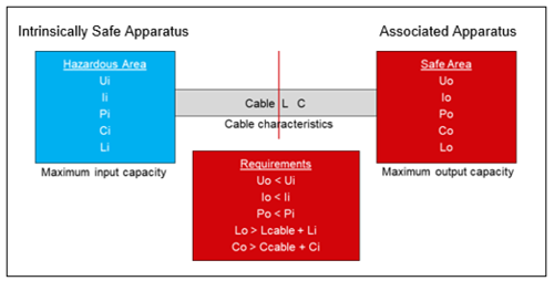
I.S. Entity Parameters and Loop Calculation
A typical intrinsically safe circuit or I.S. loop consists of 3 main components that must be considered:
- Intrinsically Safe Apparatus - certified field devices installed in the hazardous area.
- Associated Apparatus - devices installed in the safe area which interface with devices in the hazardous area e.g. I.S. barrier.
- Field Wiring – compatible interconnecting cable.
Safe design of Intrinsically Safe Circuits requires an "I.S. loop" calculation.
Specific characteristics or “entity parameters” are available for each component or device in the loop. The values can be found in the product certificate and installation drawings.
The simple I.S. loop calculation can then be used to determine what devices can safely be connected, together with maximum interconnecting cable length.
The typical entity parameters for each component of the loop are shown in the table below.
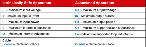
The values for associated apparatus are compared with the corresponding values for the intrinsically safe apparatus to determine whether the devices are compatible. A calculation is then done to determine the maximum cable length based on the relevant capacitance and inductance values.
The I.S. loop requirements are shown below: