SIL Part 1: Random Hardware Integrity
SIL achievement requires that the design of a safety function meets three specific criteria as outlined in the standard. This section will concentrate on number 1 – Random Hardware Integrity.
What is functional safety?
Functional safety is the active detection of potentially dangerous conditions, resulting in a demand of a protective mechanism or function to prevent or reduce the impact of hazardous events that might occur.
Forming part of the overall safety of equipment under control (EUC), functional safety has focus on electronics and related software.
IEC 61508 is an international standard for “Functional Safety or electrical/electronic/programmable electronic safety-related systems”. As the umbrella standard for functional safety, it forms the foundation of many industry specific derivatives such as IEC 61511 for the process industry.
Following a safety lifecycle model, the standards formalize the management of functional safety and provide measures and techniques for the design of Safety Instrumented Systems (SIS) and associated Safety Instrumented Functions (SIF).
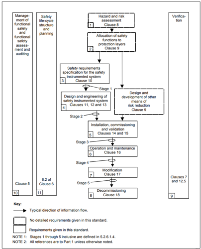
IEC 61511 Safety lifecycle
A key element of the safety lifecycle is the creation of the Safety Requirement Specification (SRS). Based on inputs from the hazard and risk assessment stages of the lifecycle, this document is the blueprint for the functionality, integrity and validation of the safety system design.
What is SIL?
The Safety Requirement Specification will document the level of any residual risk reduction required of the safety system design and assign a corresponding target SIL level.
SIL or Safety Integrity Level, is a relative level of risk reduction provided by a safety function. Four separate SIL levels from 1 to 4 are defined, with SIL 4 offering the highest level of safety integrity and corresponding risk reduction factor.
| SIL | Risk Reduction Factor - RRF |
| 4 | > 10,000 to ≤ 100,000 |
| 3 | > 1000 to ≤ 10,000 |
| 2 | > 100 to ≤ 1,000 |
| 1 | >10 to ≤ 100 |
How is a specific SIL achieved?
SIL achievement requires that the design of a safety function meets three specific criteria as outlined in the standard.
These strict criteria are: Random hardware integrity, Architectural constraints and Systematic capability
This section will concentrate on number 1 – Random Hardware Integrity. For information on Architectural Constraints and Systematic Capability please click on the relevant links.
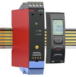
PR electronics offers a range of SIL certified devices to cover a wide selection of SIL applications.
What is random hardware integrity?
Random hardware integrity relates to random hardware failures. If safety systems were 100% reliable then residual risk would be reduced to zero and all systems would be 100% safe.
This is not achievable, and as such we need to quantify the likelihood of a safety function failing when a demand is placed upon it. Understanding this will allow us to determine the level of risk reduction it is likely to offer.
Safety Instrumented Functions (SIF’s) which operate in “Low Demand” mode use the Average Probability of Failure On Demand (PFDavg) metric to quantify reliability, while “High” or “Continuous Demand” SIF’s use Probability of Failure per Hour (PFH).
Table 4 from IEC 61511 details how these values correspond to risk reduction factor (RRF) offered for Low Demand SIF’s:
| SIL | Risk Reduction Factor – RRF | PFDavg Range |
| 4 | > 10,000 to ≤ 100,000 | ≥ 10-5 < 10-4 |
| 3 | > 1000 to ≤ 10,000 | ≥ 10-4 < 10-3 |
| 2 | > 100 to ≤ 1,000 | ≥ 10-3 < 10-2 |
| 1 | >10 to ≤ 100 | ≥ 10-2 < 10-1 |
IEC 61511 - Table 4
Table 5 shows the correspondent values for High/Continuous Demand SIF’s:
| SIL | Probability of Failure per Hour – PFH |
| 4 | > 10-9 ≤ 10-8 |
| 3 | > 10-8 ≤ 10-7 |
| 2 | > 10-7 ≤ 10-6 |
| 1 | > 10-6 ≤ 10-5 |
IEC 61511 - Table 5
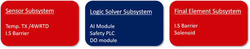
Calculating a PFDavg of a Safety Instrumented Function requires analysis of its constituent parts. A typical SIF is made up of a sensor subsystem, logic solver and final element subsystem.
Examples of SIF components are shown below:
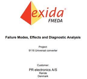
Failure analysis techniques such as FMEDA (Failure Modes Effects and Diagnostics Analysis) are widely used to determine the failure modes and diagnostic capabilities of individual devices.
Failure rate data can be combined with additional variables to calculate a probability of failure across a defined mission time.
Although simple equations exist for calculating PFD, the more variables that are included in the calculation the more accurate and safer the result will be.
Variables to consider in PFD calculations:
| Variable | Source |
| Device failure rates (eg λDU, λDD) | Usually supplied by the manufacturer via an FMEDA report |
| Mission Time (MT) | Determined by the end user |
| Proof Test Interval (TI) | Determined by the end user |
| Proof Test Coverage (CPT) | Determined by the end user or advised by manufacturer |
| Proof Test Duration | Determined by the end user |
| Mean Time to Restore (MTTR) | Determined by the end user |
| Common Cause Failures (CCF) | Beta factor to consider when using redundancy |
Example Low Demand mode PFDavg equation
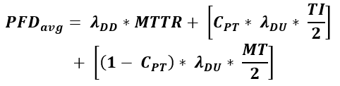
The PFDavg of a Safety Instrumented Function is the total of all subsystem PFDavg values
| Sensor subsystem | Logic solver | Final element |
 |
 |
 |
| 1.5 x 10⁻³ | 8.6 x 10⁻⁵ | 1.8 x 10⁻² |
Total SIF PFDavg = 1.9 x 10-2 = SIL
High or Continuous Demand mode SIF’s use PFH (Probability of Failure per Hour) for their calculation
![]()
Achieving the target PFDavg/PFH for a safety function does not in itself prove target SIL achievement. Consideration must also be given to Architectural Constraints and Systematic Capability.
