
Advantages of converting RTD and Thermocouple signals to 4…20 mA current
Thermocouple and RTD sensors are commonly used to measure temperature in industrial processes. In cases where these sensors are connect directly to the PLC, the result of the measurement accuracy is sometimes worse than expected. This loss of accuracy is often caused by electromagnetic interference, (EMI). By converting thermocouple and RTD signals to industry standard 4…20 mA current, however, errors due to EMI can be effectively eliminated.
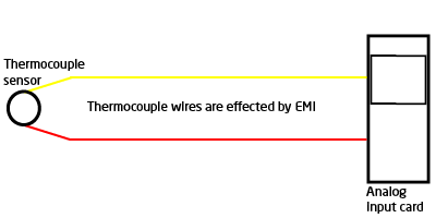
Most thermocouples create a voltage signal of less than 50 mV, and a thermocouple has practically no ability to create a current flow. Therefore, any device that measures a thermocouple must have a very high input resistance, (usually 1 million Ω or more).
The combination of a low mV signal and no current flow makes thermocouples behave like an antenna. Electrical noise from 50/60 Hz power mains, burst noise from lightning, static electricity, radio frequency interference from portable radios, commutator noise from DC motors and many other sources of electrical noise can be “received” by a thermocouple – and the longer the wires are, the more opportunity there is to “receive” electrical noise.
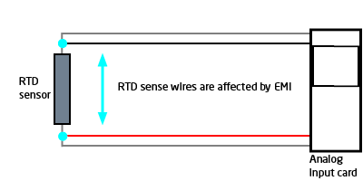
The same thing can happen when measuring RTDs. Even though the RTD element is excited by a tiny constant current source, (typically 0.3 mA), virtually no current flows on the sense wires used on 3- and 4-wire RTDs. Therefore, the sense wires also act like antennas, picking up a wide range of noise present in the industrial environment.
Some symptoms of noise-affected temperature signals are that temperature measurements:
- immediately change when a nearby motor or heater starts.
- change when a part of a process is turned off or on.
- change when a mobile radio is transmitting.
- change based on time of day or weather patterns.
- change based on the location/orientation of sensor wiring.
How to minimize errors caused by EMI
One of the best ways to minimize error due to EMI, is to minimize the length of the sensor wiring, thereby minimizing the length of the “antenna”.
This is accomplished by measuring the thermocouple or RTD signal at the sensor and converting that measurement to a 4…20 mA current. The current is then measured by a PLC input card that has approximately 250 Ω resistance. Doing this will eliminate error due to EMI.
![]()
The current flow through one side of a current loop will be affected by EMI created by, say a portable radio. This EMI might assist (increase) the normal flow of current on that side of the loop. However, the current on the other side of the loop is flowing in the opposite direction through the same electromagnetic field. Because of this, the current flowing through that side of the loop is countered, (decreased), by the EMI. The net effect: Loop current flow is practically unchanged by EMI.
Accuracy is further improved by twisting the loop conductors around each other. This ensures both wires are equally shielded from the electromagnetic interference, and the twisted conductors form a series of magnetic fields in opposition to each other along the length of cable. Both effects ensure that all sources of EMI have an equal - but opposite - effect on loop current. Because of these effects, 4…20 mA loops can pass through areas of significant EMI with virtually no disturbance in the measured signal.
![]()
In some applications, the sensor wires going to the control panel are not affected by EMI, but a high level of electromagnetic interference exists inside the panel. This interference is created by things like variable frequency motor drives, SCR motor and heater controllers, electric motor soft starters, high voltage contacts, and DC motor drives.
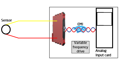
The effects of EMI inside the panel can be minimized by using a DIN rail mounted temperature transmitter to convert low level RTD and thermocouple signals to robust 4…20 mA. The isolation provided by the temperature transmitter also virtually eliminates error caused by common mode noise (electrical interference common to both sensor wires). This solution allows the original sensor wiring to remain undisturbed, while improving the accuracy and repeatability of the measurement made by the analog input card.
Two transmitter solutions
It is advantageous to use two transmitters: one at the sensor, and another inside the control panel. This solution provides excellent immunity to EMI because the length of sensor wires is minimized, plus the panel transmitter can perform many different functions inside the panel:
![]()
- The panel transmitter can provide an independent, isolated, mA output, plus alarm contacts to PLC analog and digital input cards
- The panel transmitter can be equipped with a backlit display showing the process value, relay status, and sensor/loop errors. This greatly reduces troubleshooting and commissioning time
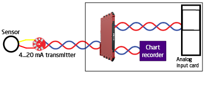
- The panel mounted transmitter can split the signal, providing multiple, isolated, active or passive 4…20 mA current signals to several devices in the plant.
-
In addition, PR transmitters can perform signal dampening, multipoint linearization of non-linear inputs, (like thermistors), volume measurement of odd shaped tanks, math functions on two input signals, and much more.