
8 tips and advice for reducing the effects of EMI on your instrumentation signals
Electromagnetic interference, or EMI, is commonly found in industrial environments, and can adversely affect the accuracy of your instrumentation signals – here are some tips and advice that can help ensure accurate measurements in environments with high levels of noise.
Some electromagnetic interference sources found in industry settings are: Variable frequency drives, soft start motor starters, SCR heater controllers, power and auxiliary contacts, AC and DC motors, AC and DC generators, switching power supplies, power wiring, which radiates 50 Hz/60 Hz noise, walkie talkies, arc welding, fluorescent bulb ballasts, electrostatic discharge, lightning… and many more.
How to reduce the effects of EMI noise
Here are some tips for reducing the effects of EMI on your instrumentation signals:
1. Always run power wiring and instrument signal wiring in separate conduits or separate cable trays. Maintain this separation as much as practical in the control panel.
2. If instrument wiring must cross over power wiring, cross at a 90 degree angle while maintaining as much separation as possible.
3. Avoid forming loops in instrument wiring… the wire should run as straight as possible.
4. Use twisted pair shielded cable to carry instrumentation signals. Twisting the wires equalizes the effect of EMI on both wires, greatly reducing error due to EMI. Surrounding the instrument wires with a shield protects them from EMI, and provides a path for EMI-generated current to flow into ground.
5. Connect one end of the shield to ground, preferably the ground point that has the least electrical noise.
6. A current signal is inherently more immune to EMI than voltage signal, so it is beneficial to use an isolated transmitter to convert signals into industry standard 4-20 mA current. This provides the following advantages:
- 4...20 mA signals are highly immune to electrical noise.
- Unlike voltage signals, 4-20 mA signals will not attenuate over a long distance, (within limits).
- Most transmitters can be programmed to regulate loop current to an unusually high or low level if the sensor fails. Typically, these limits are 3.5 and 23 mA. In this way, a 4-20 mA signal can notify the system of a sensor error.
- A broken cable wire will result in 0 mA current flow, which makes it easy to detect a cable error. If voltage signals are used, the high impedance of the downstream instrument makes the broken wiring act like an antenna. EMI can easily induce a voltage onto the wires, making cable break detection unreliable when voltage signals are used.
- Isolating the measurement protects downstream equipment from damage due to high common mode voltage, and eliminates error due to ground loops.
- Isolating the measured signal will block EMI that is common to both input wires.
- Most transmitters have adjustable output dampening, which allows you to filter out signal instability caused by EMI.
7. In the control panel, minimize the length of unshielded instrumentation wires. Make sure the exposed wires remain tightly twisted all the way to their connection points.
8. In the control panel, route instrumentation cables away from sources of EMI in the panel. Thermocouple and RTD signals are especially prone to error caused by EMI, so be careful where these cables are routed in the panel.
Following these guidelines will help ensure accurate measurements in environments with high levels of EMC (electromagnetic compatibility).
PR electronics has always been a pioneer in EMC... Read more...
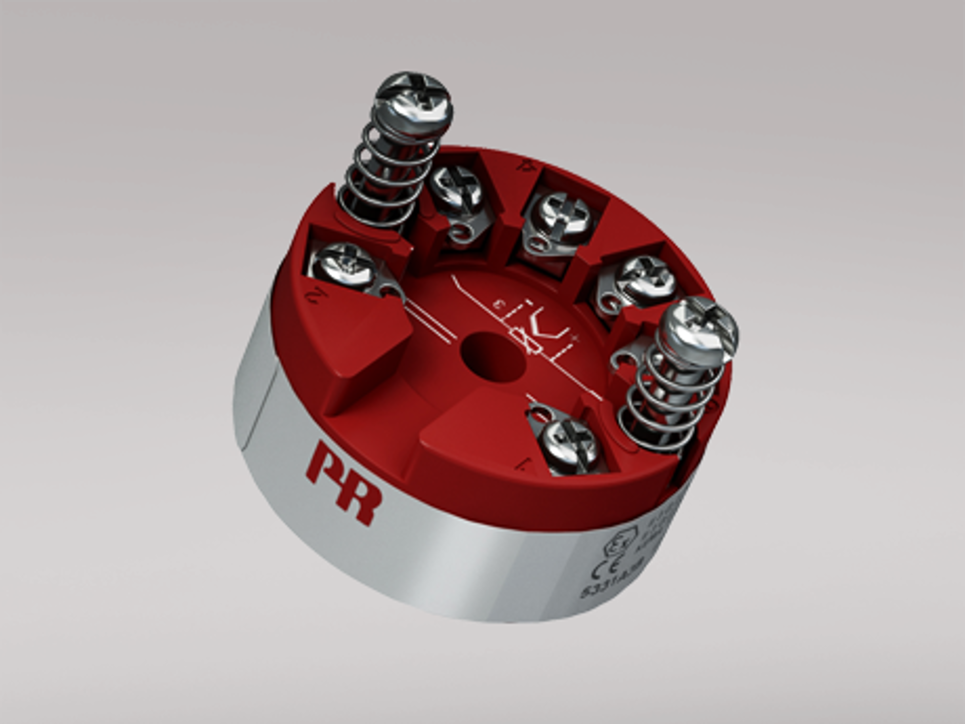
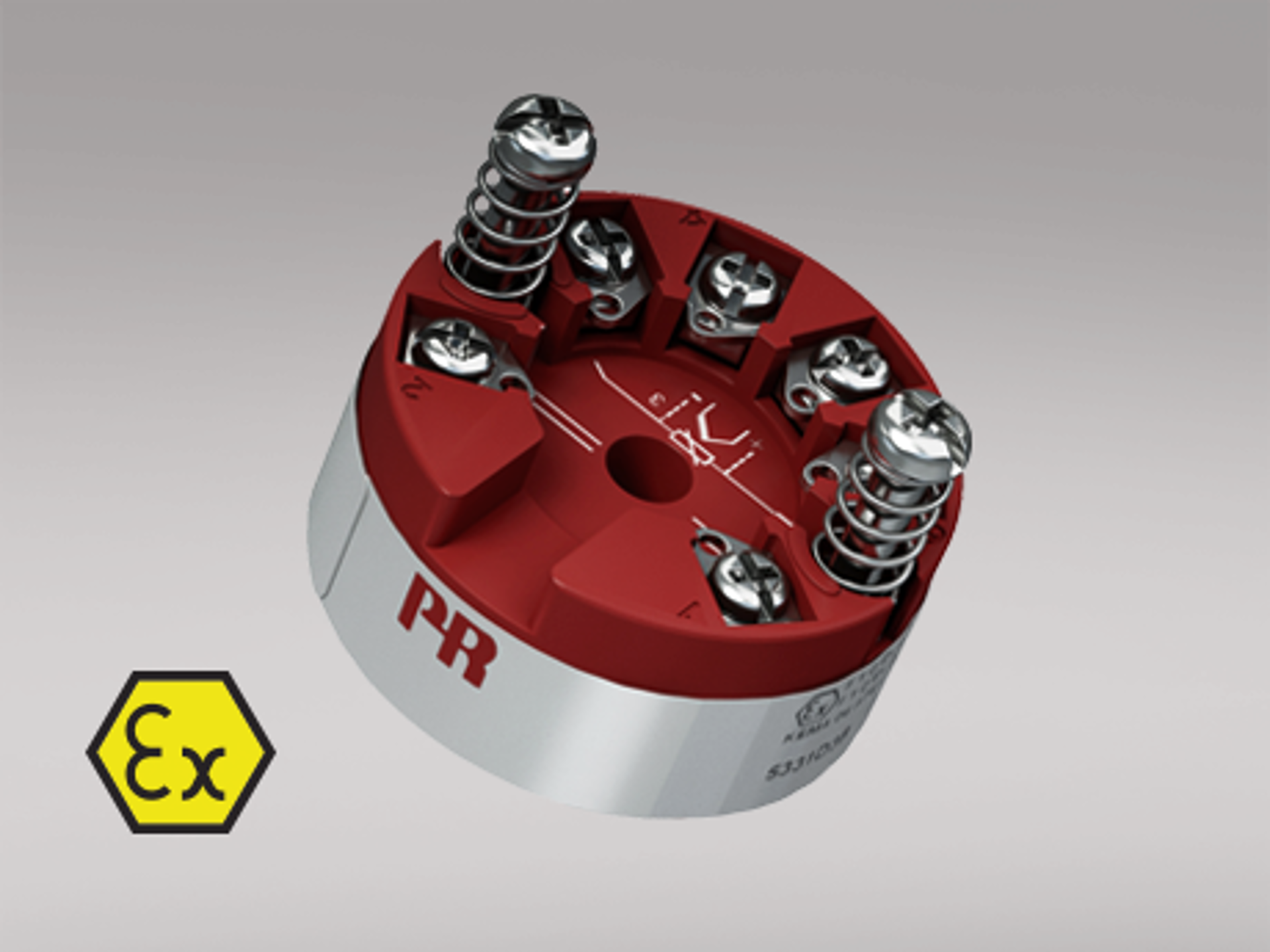
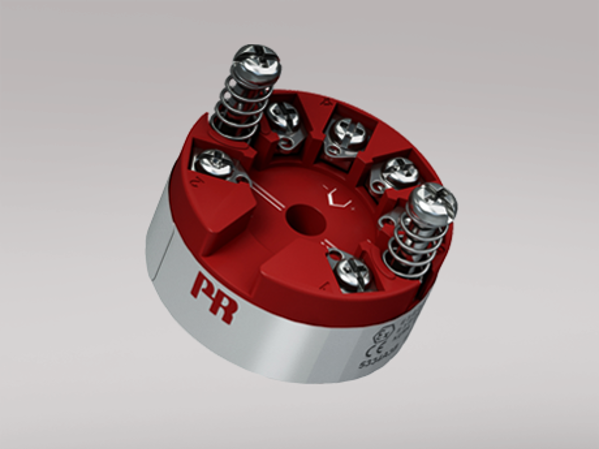
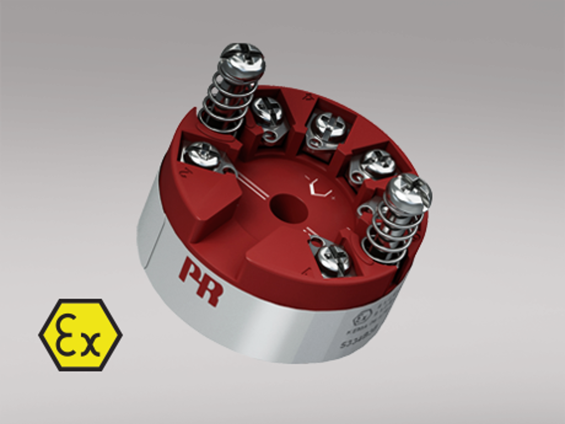
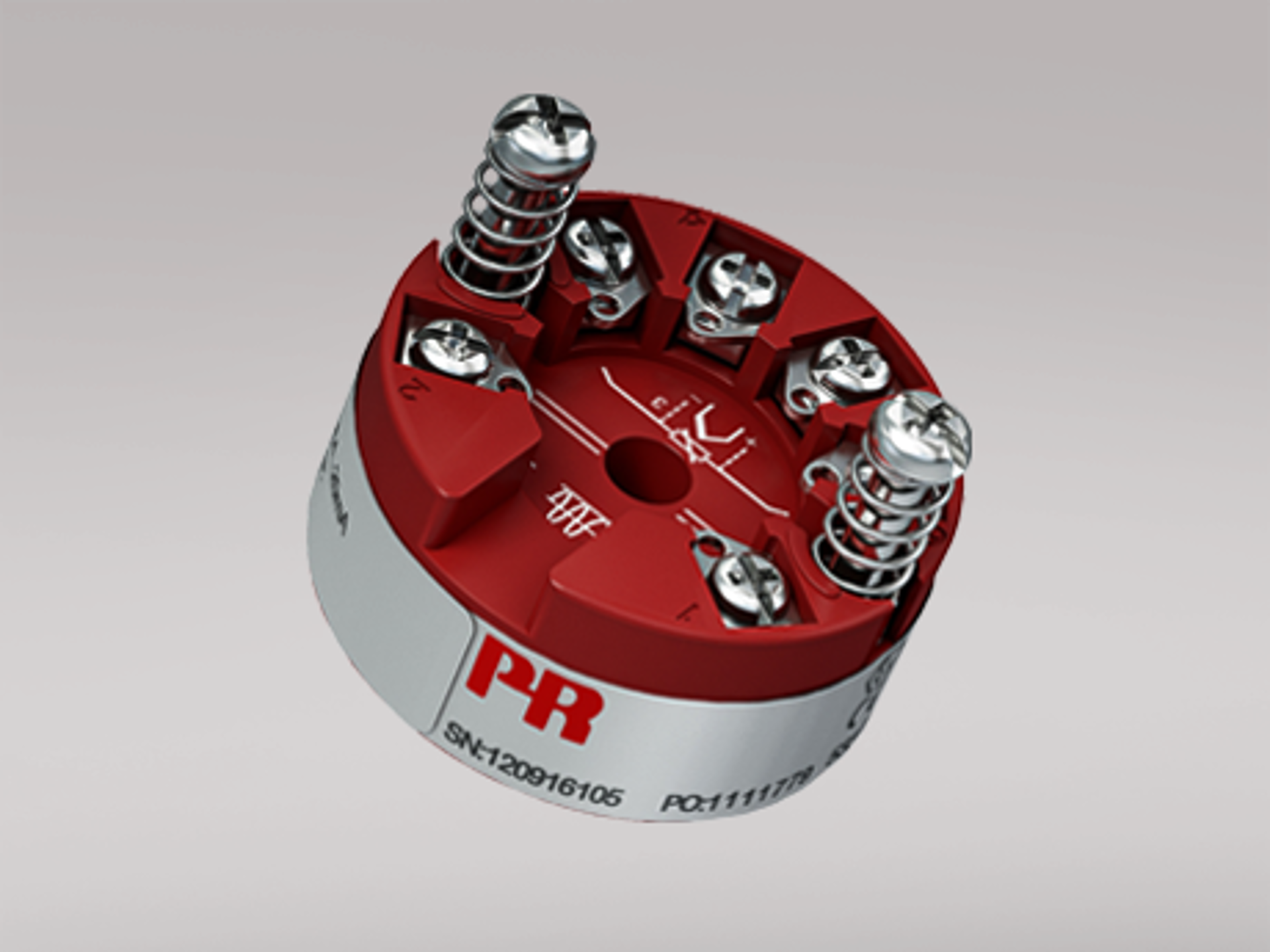
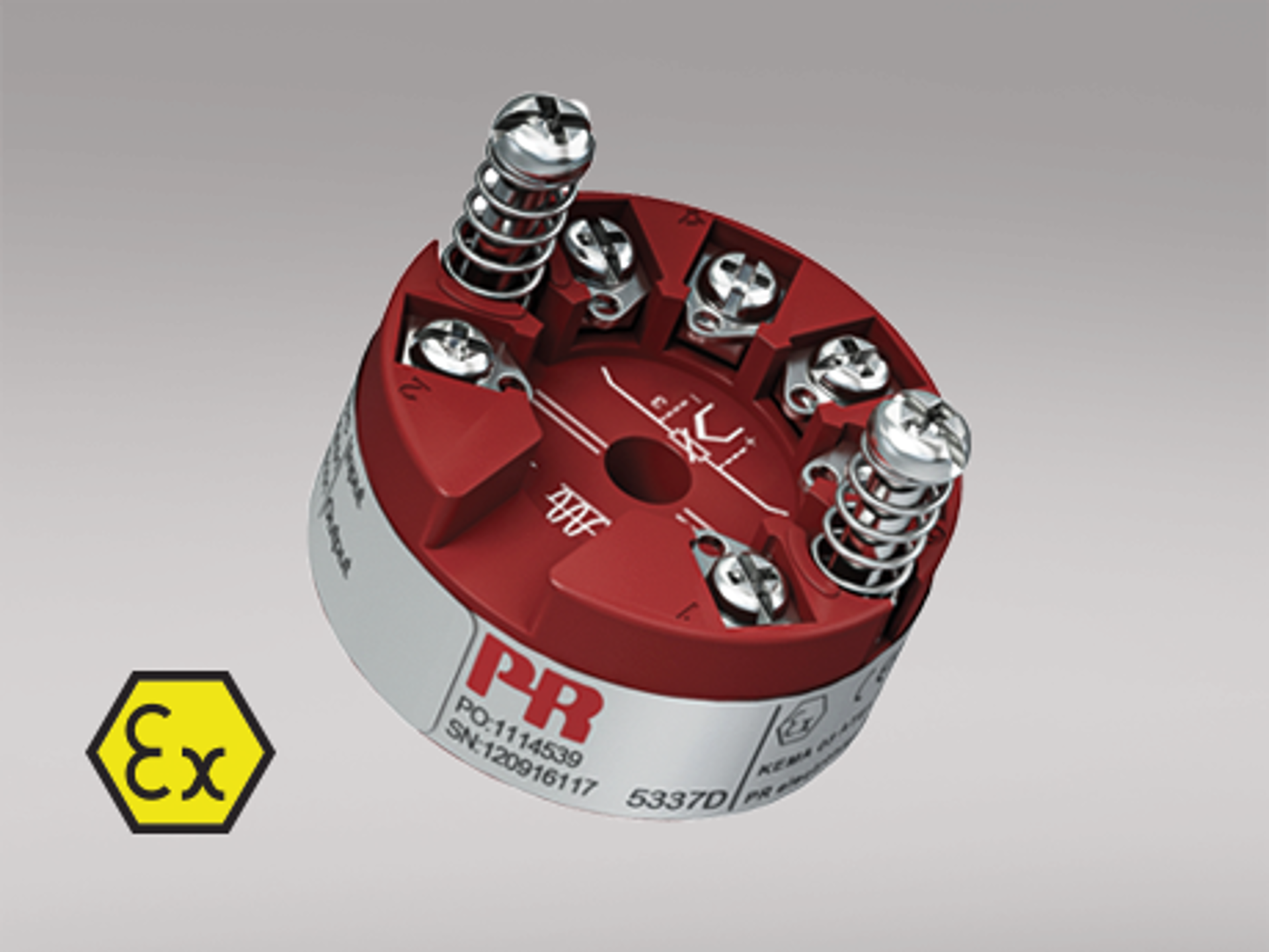
Examples of isolated head mounted temperature transmitters:
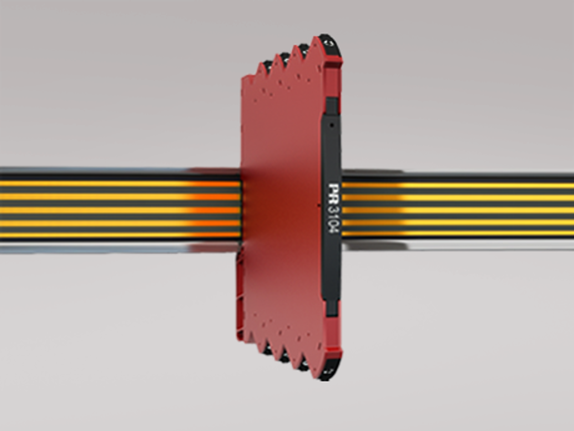
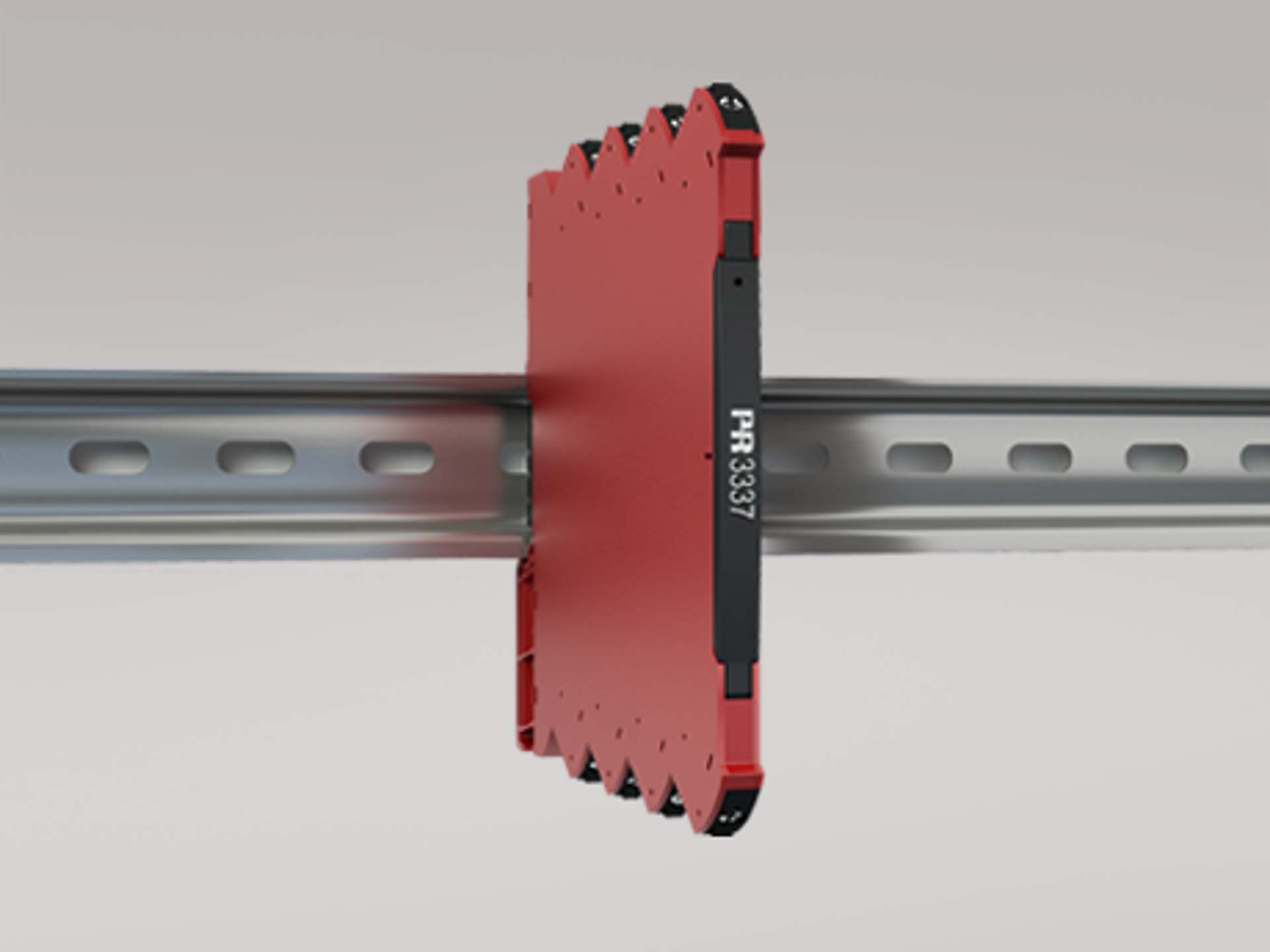
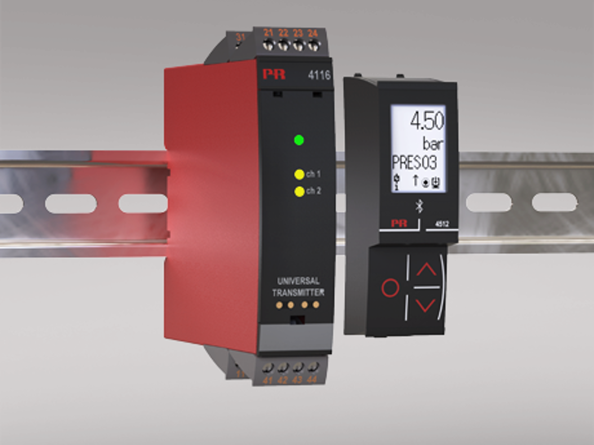
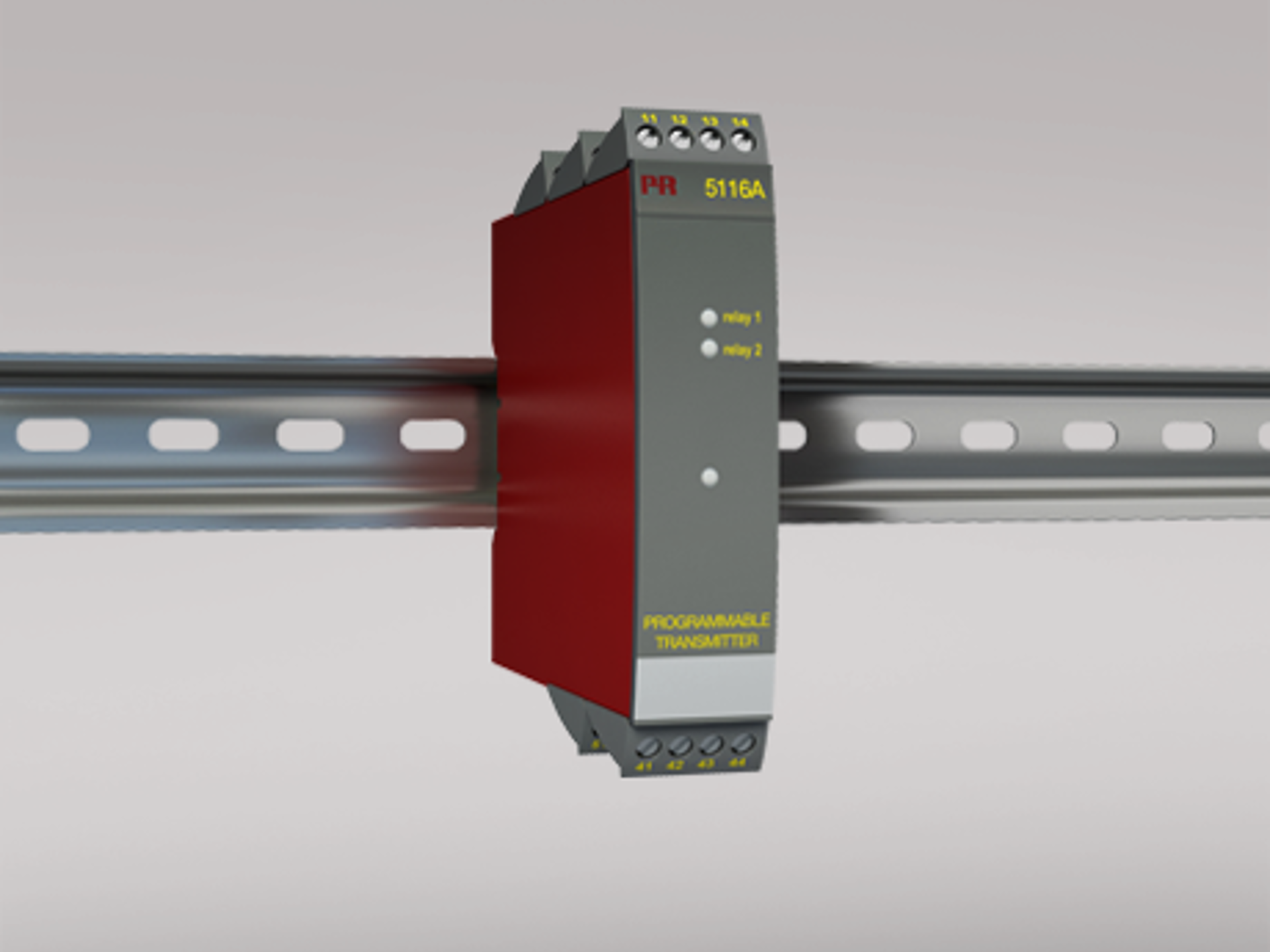
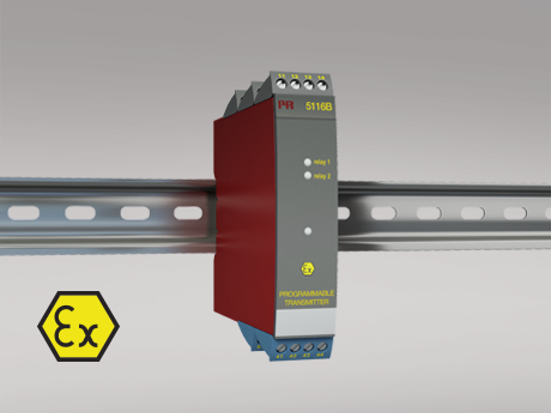
Examples of isolated DIN rail mounted transmitters:
What is EMI?
EMI refers to the term Electromagnetic Interference. Electromagnetic interference from natural phenomena such as lightning or from one electronic device to another through conduction or radiation. EMI can affect the normal operation of electrical devices and should be minimized.
What does EMI stand for?
EMI refers to the term Electromagnetic Interference
What does EMI mean?
EMI refers to the term Electromagnetic Interference
What is EMI in electronics?
This refers to conducted or radiated electromagnetic interference experienced or generated by electronic circuitry or devices whilst in operation
What is EMI filter?
An EMI filter is a device used to reduce typically conducted electromagnetic interference. This is achieved by suppressing high frequency transients in power and signal lines.
What is EMI shielding?
EMI shielding is used to protect circuitry and cabling from radiated elecromagnetic interference. Shielding is normally a formed metallic screen designed to absorb EMI and to prevent it affecting sensitive signals or electronics.

Pentronic - Sweden: "… in one of our projects we had issues relating to a noisy environment. The electrical noise affected the accuracy of the temperature measurement. We then decided to use a PR transmitter and that solved the problem”."


Cool Clean Technologies - USA:
"Electrical noise generated by other analog signals and automation equipment is not an issue we have to deal with when using PR converters..."

If you require assistance in finding the right device, please don't hesitate to contact us.