Intrinsically safe barriers: Ensuring safe and reliable signal transmission
What is an I.S. interface?
An I.S. interface, also commonly referred to as intrinsically safe galvanic isolators or intrinsically safe barriers; are devices used to interface hazardous area process signals with safe area control equipment. Our selection of I.S. interfaces are designed to comply with global standards and directives including ATEX, IECEx, FM and UL.
If you require assistance in selecting the device that is just right for your application, please do not hesitate to contact us.
- 24 VDC supply via power rail or connectors
- Active and passive mA input
- SIL2 / SIL3 Full Assessment

- 24 VDC supply via power rail or connectors
- High active output load 725 Ohm / 20 mA
- SIL2 certified via Full Assessment

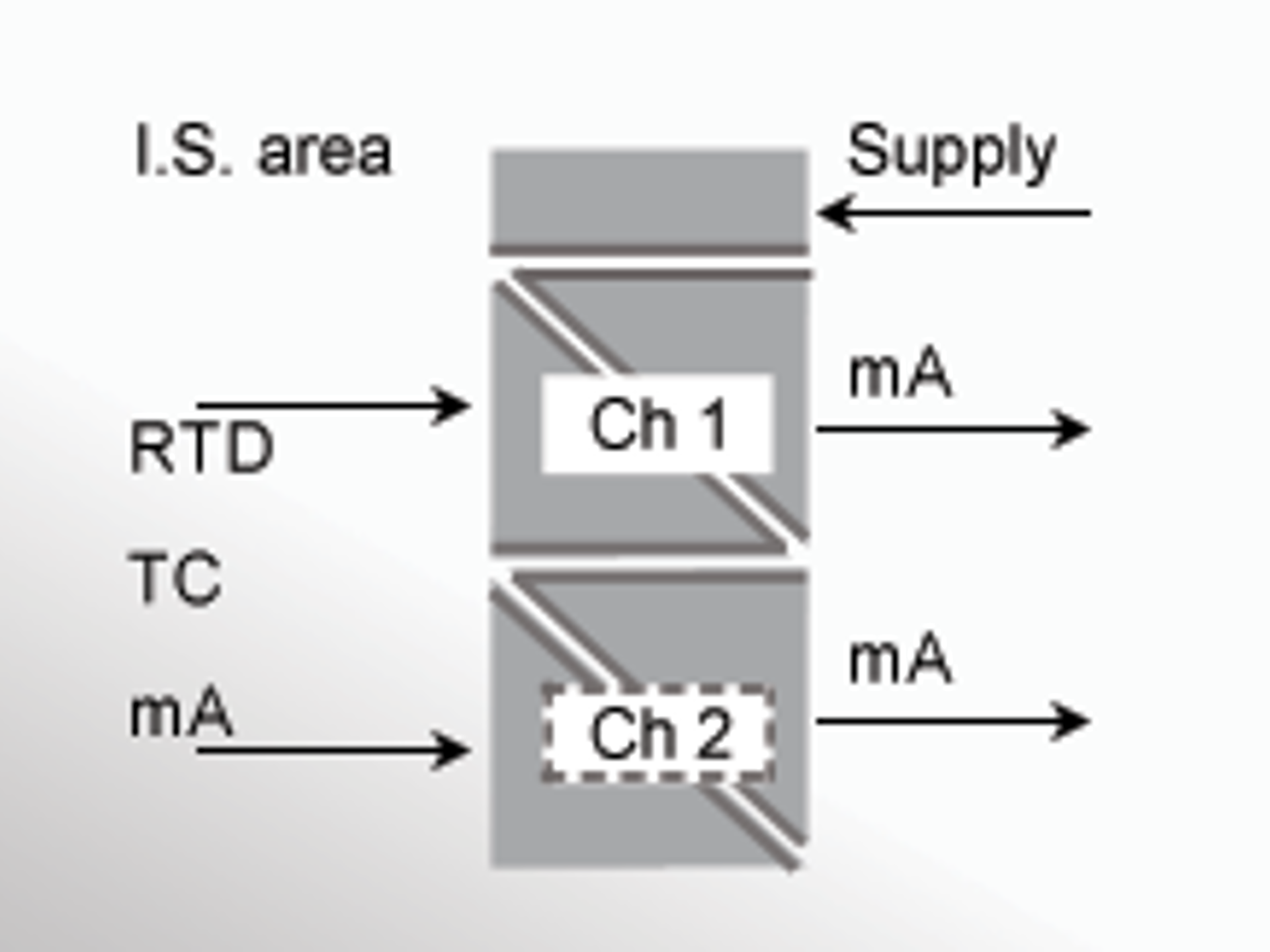
- 1 or 2 channels
- Can be supplied separately or installed on power rail, PR type 9400
- SIL 2-certified via Full Assessment
- 1 or 2 channels
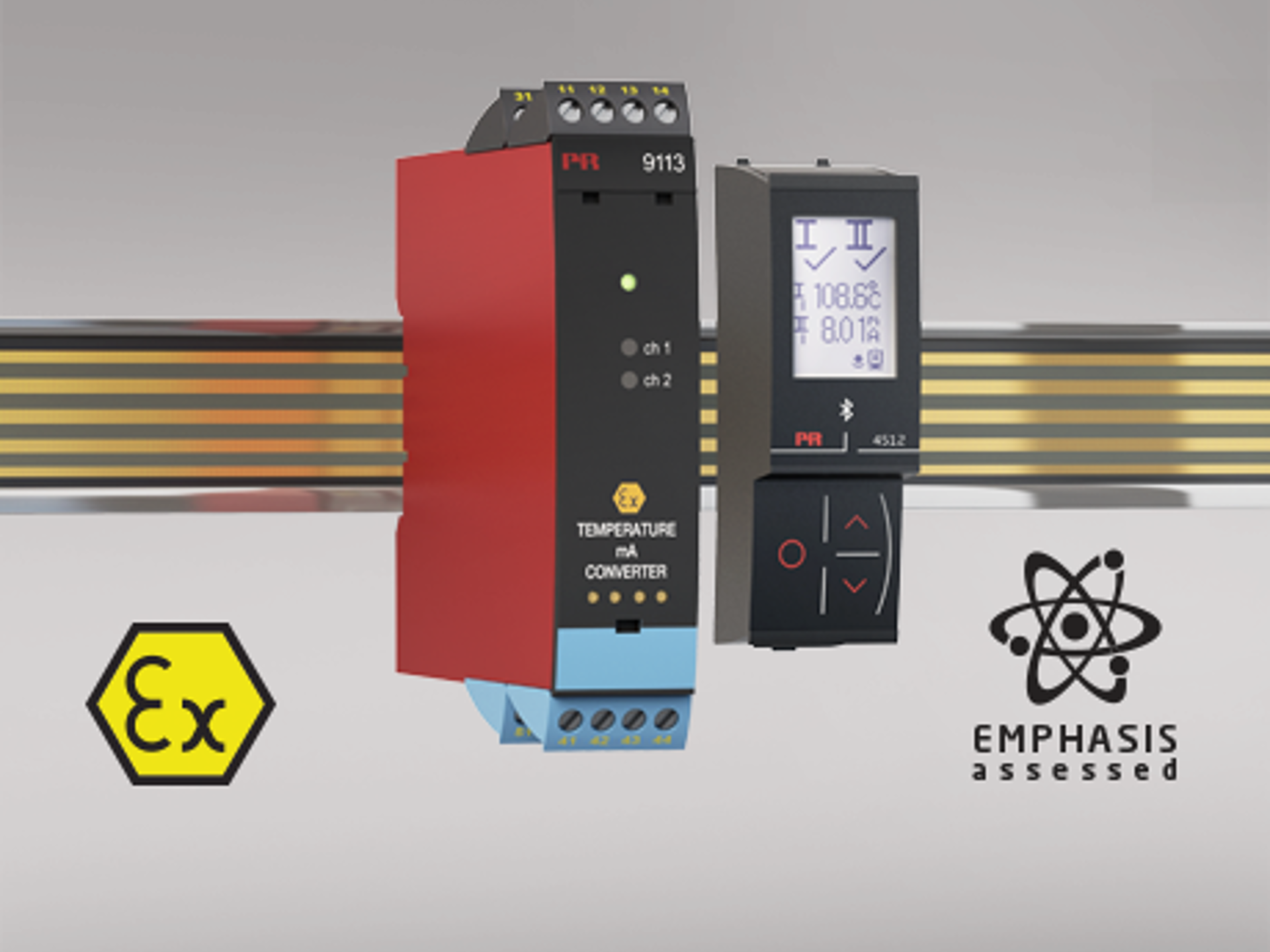
- EMPHASIS assessed instrument for nuclear industry
- SIL 2-certified via Full Assessment

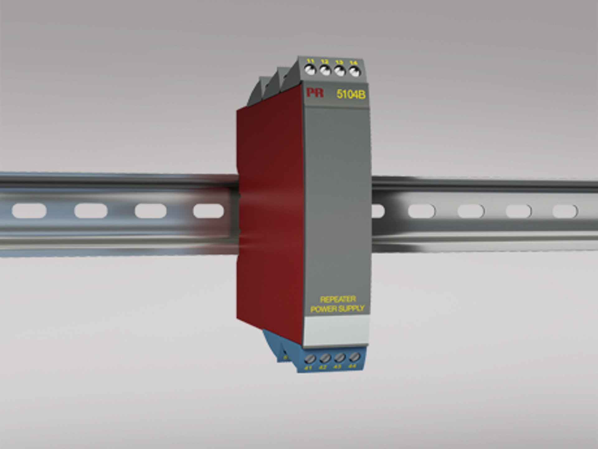
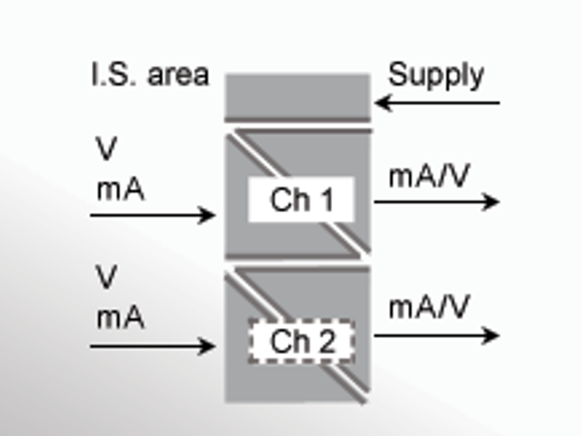
- Supply for 2-wire transmitters
- Active / passive mA output and relay output
- SIL 2-certified via Full Assessment
- Supply for 2-wire transmitters
- EMPHASIS assessed instrument for nuclear industry
- SIL 2-certified via Full Assessment

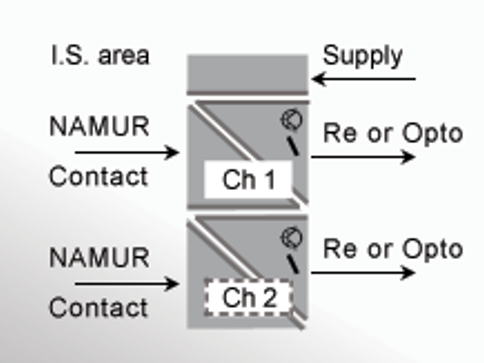
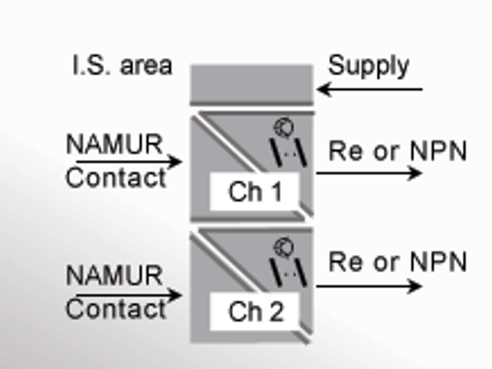
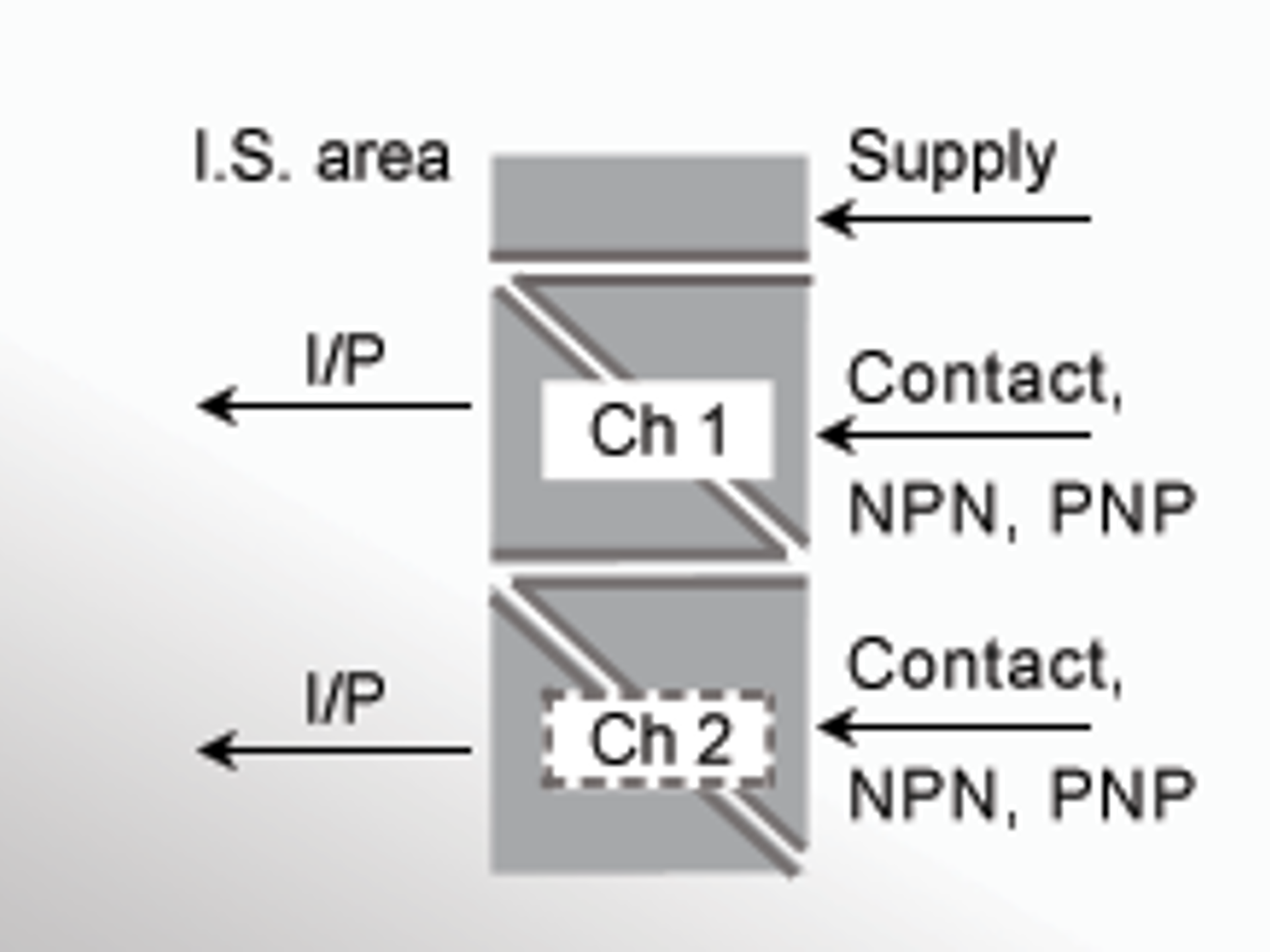
- Interface for NAMUR sensors and switches
- 1 or 2 channels
- SIL 2-certified via Full Assessment

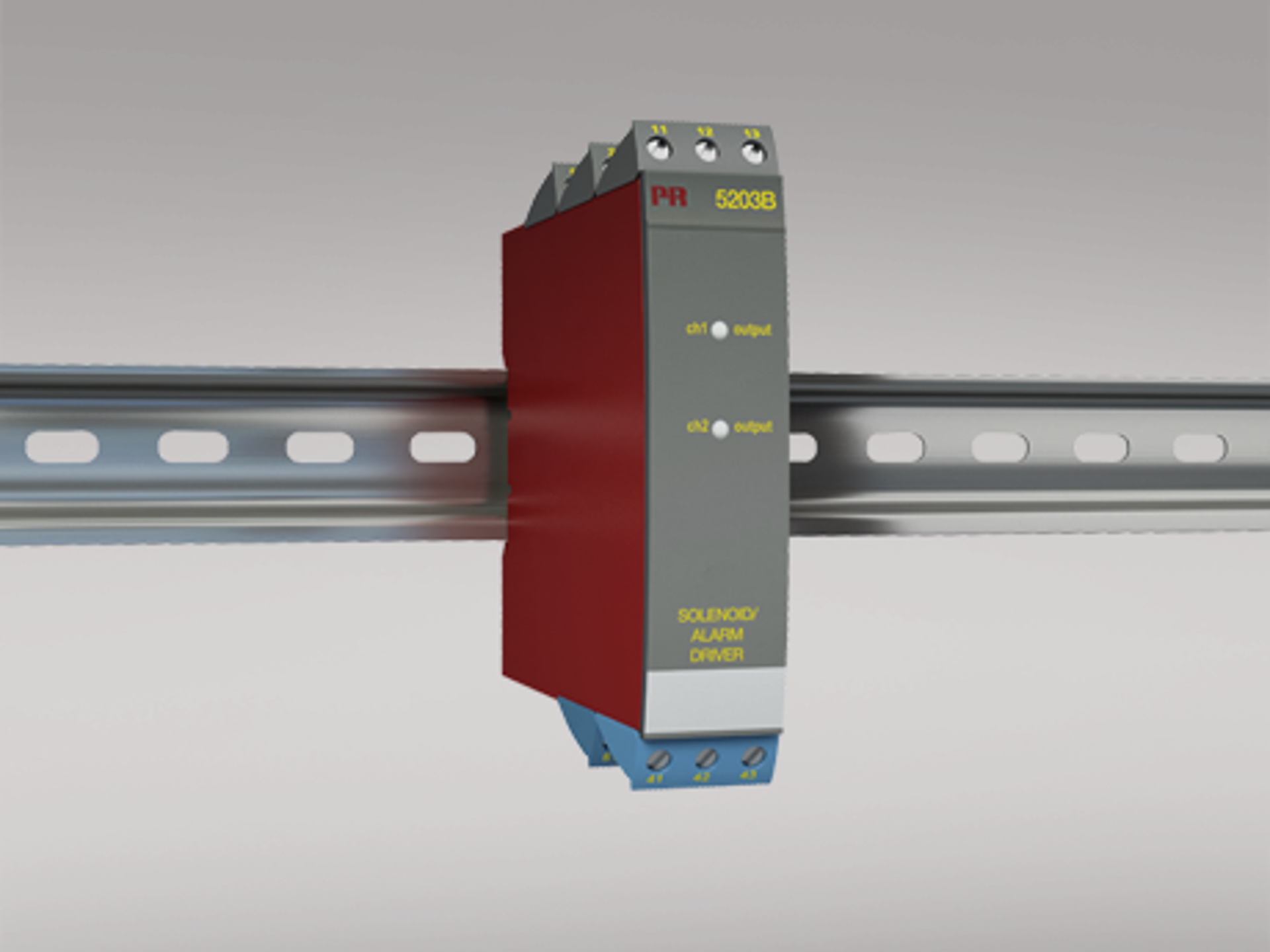
- Universal Ex driver for solenoids, acoustic alarms and LEDs
- 1 or 2 channels
- SIL 2-certified via Full Assessment
- Provides safe, easy wiring between the backplane and non I.S. automation systems
- For 8 system 9000 units
- Direct, Redundant and Duplicate signalling
- Provides safe, easy wiring between the backplane and non I.S. automation systems
- For 16 system 9000 units
- Direct, Redundant and Duplicate signalling
- UL 913-approved version for US market only
- 1- or 2-channel version
- Loop supply > 17.1 V in hazardous area
- Universal supply by AC or DC
- UL 913-approved version for US market only
- 1- or 2-channel version
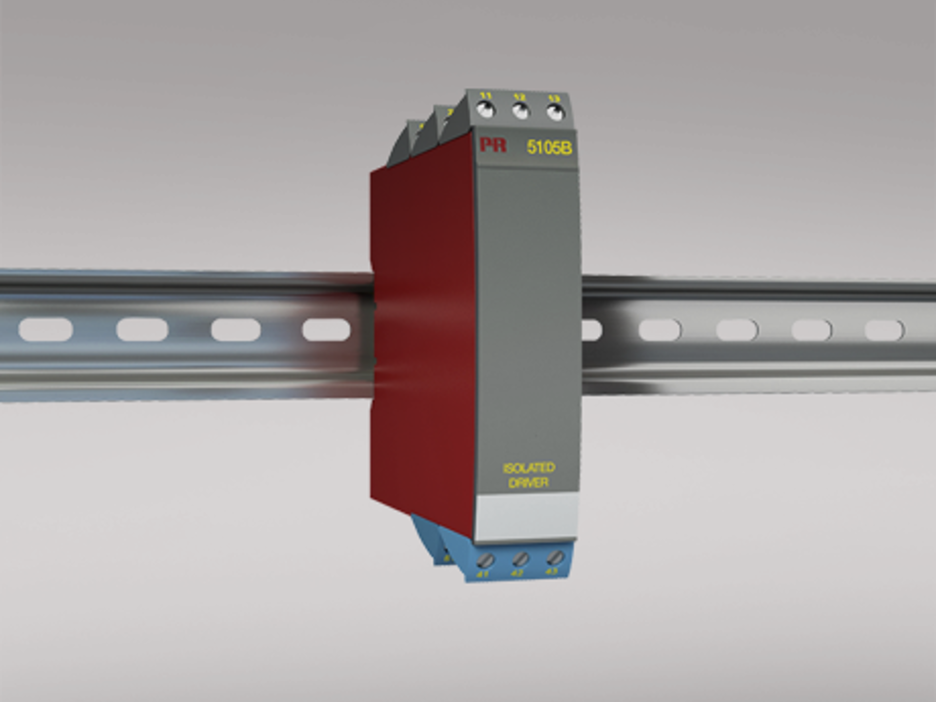
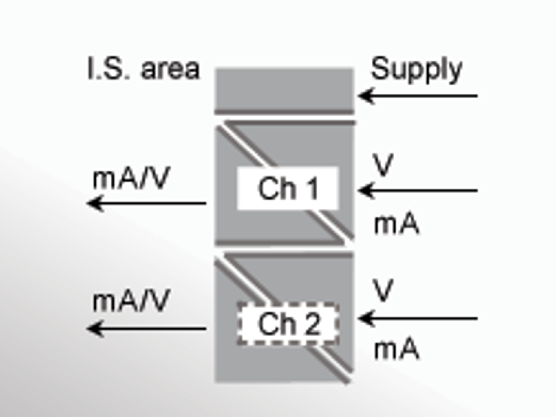
- Driver for I.S. area
- Universal supply by AC or DC
- UL 913-approved version for US market only
- 1- or 2-channel version
- 2-wire supply > 17 V in I.S. area
- Universal supply by AC or DC
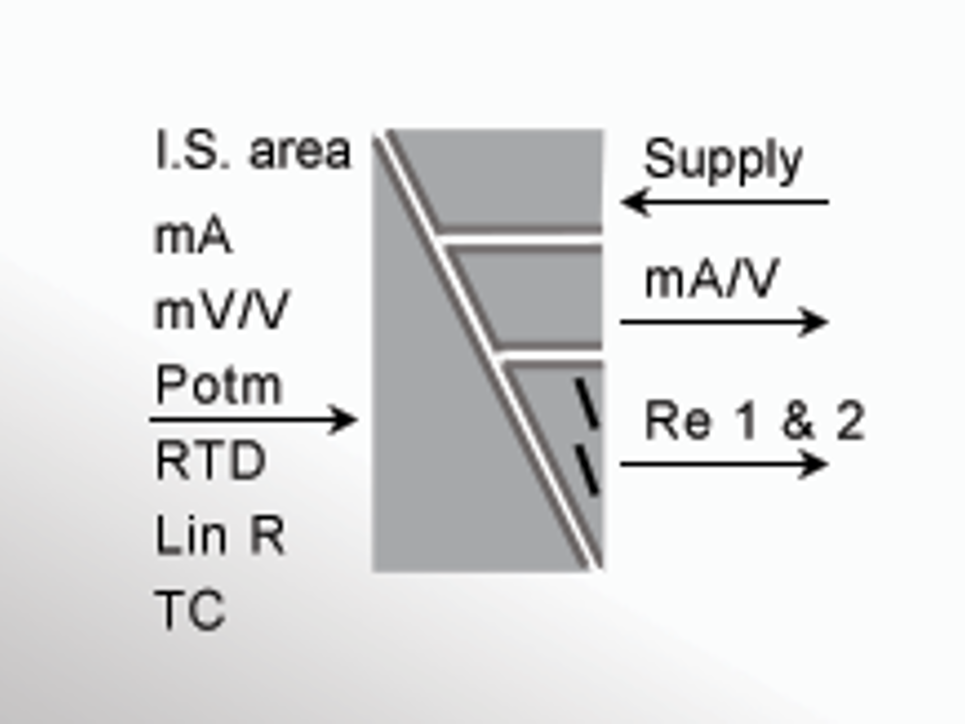
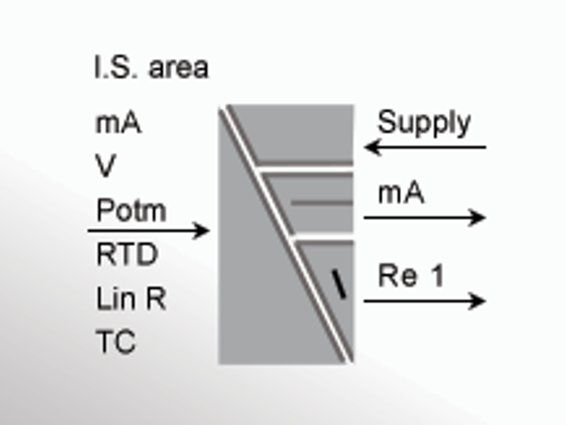
- RTD, TC, mV, Ohm, potmeter, mA, V input
- 2-wire supply > 16.5 V to Ex zone 0
- Universal supply by AC
or DC
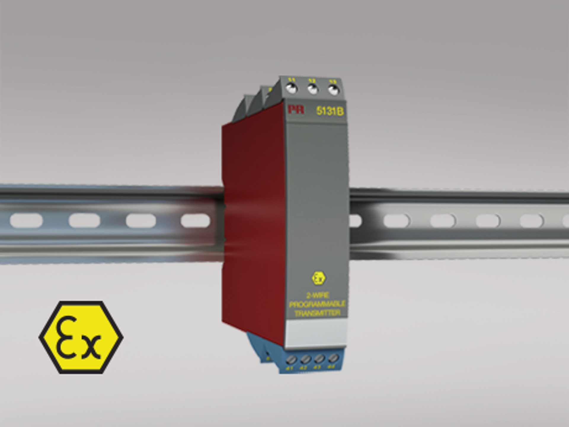
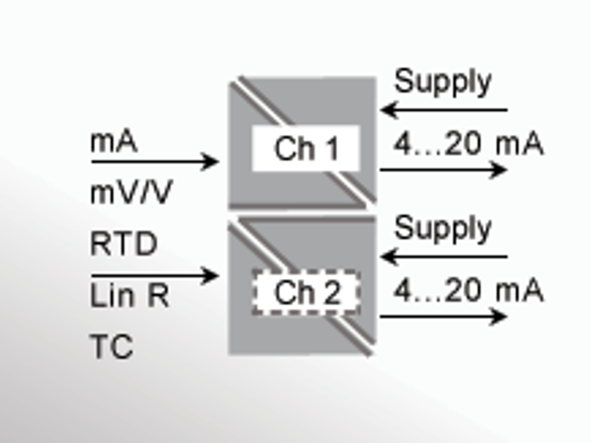
- RTD, TC, mV, linear resistance, mA, and V input
- 4...20 mA loop output
- 1- and 2-channel version
- 2 channels - 2 or 4 outputs
- Dual output
- Universal supply by AC
or DC
- UL 913-approved version for US market only
- 1- or 2-channel version
- Digitally controlled voltage supply for I.S. area
- Universal supply by AC or DC
Intrinsically safe barriers are essential components in protecting equipment and personnel in hazardous environments. These devices ensure that electrical energy supplied to the hazardous area is safe and cannot cause sparks or ignition, meeting intrinsic safety standards. When combined with devices like temperature converters, signal isolators, or RTD/TC sensors, intrinsically safe barriers enable secure and reliable operation in explosive or potentially dangerous environments.
These barriers provide galvanic isolation between hazardous and safe areas, preventing ground loops, electrical surges, and ensuring that signals remain intact while protecting the system from external electrical disturbances. Intrinsically safe barriers are widely used across industries like oil and gas, chemical processing, mining, and pharmaceutical manufacturing, where process safety and equipment reliability are critical.
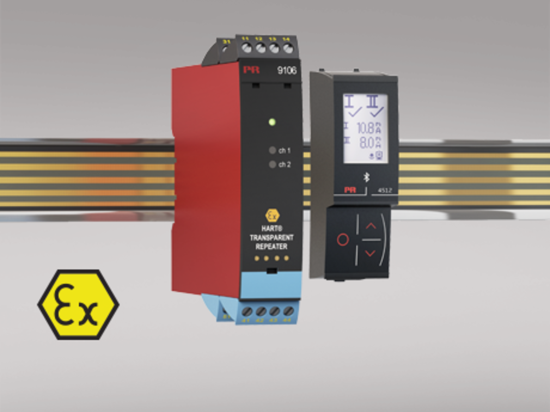
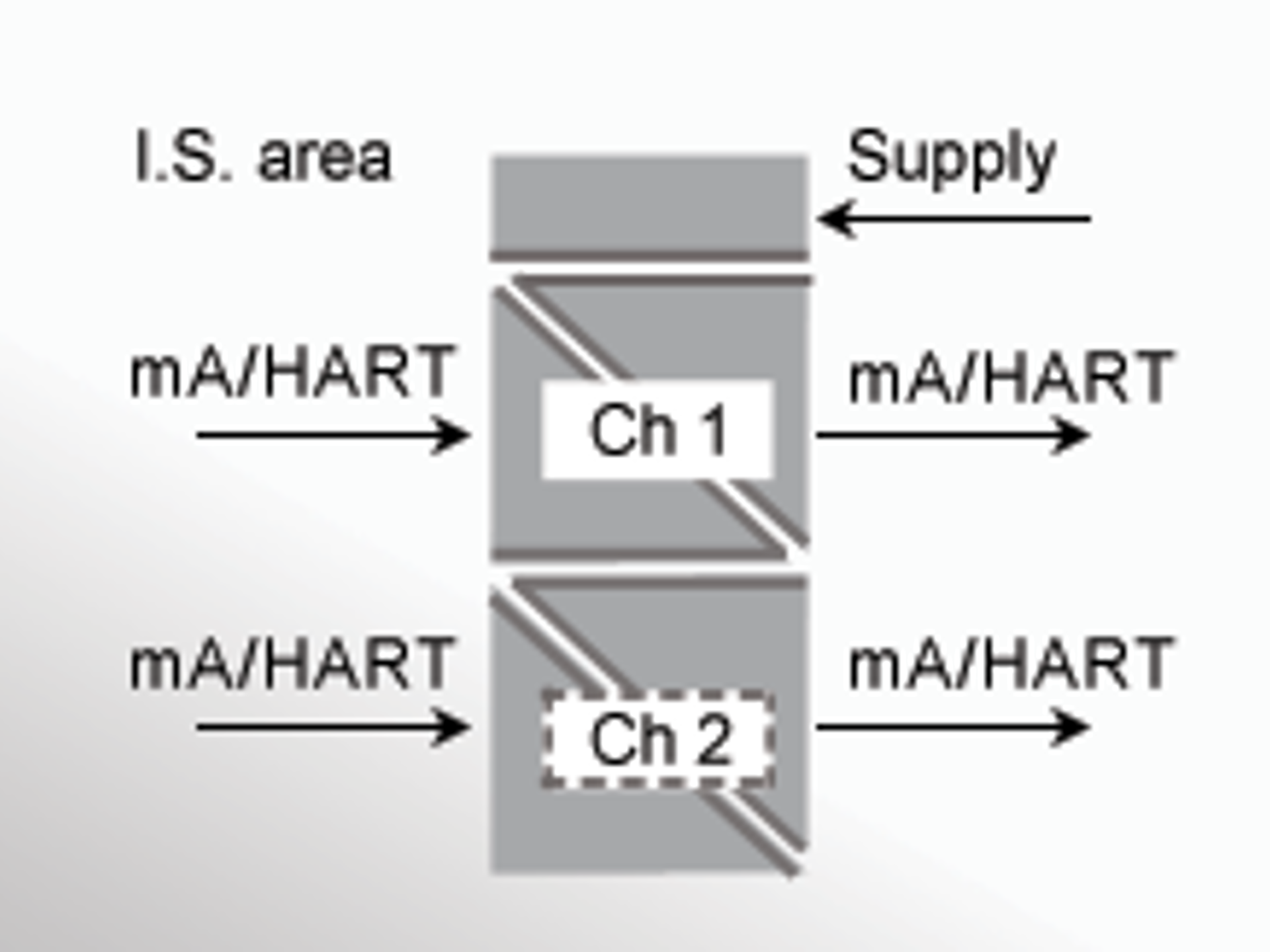
HART Transparent Repeater: Enhancing Communication in Hazardous Areas
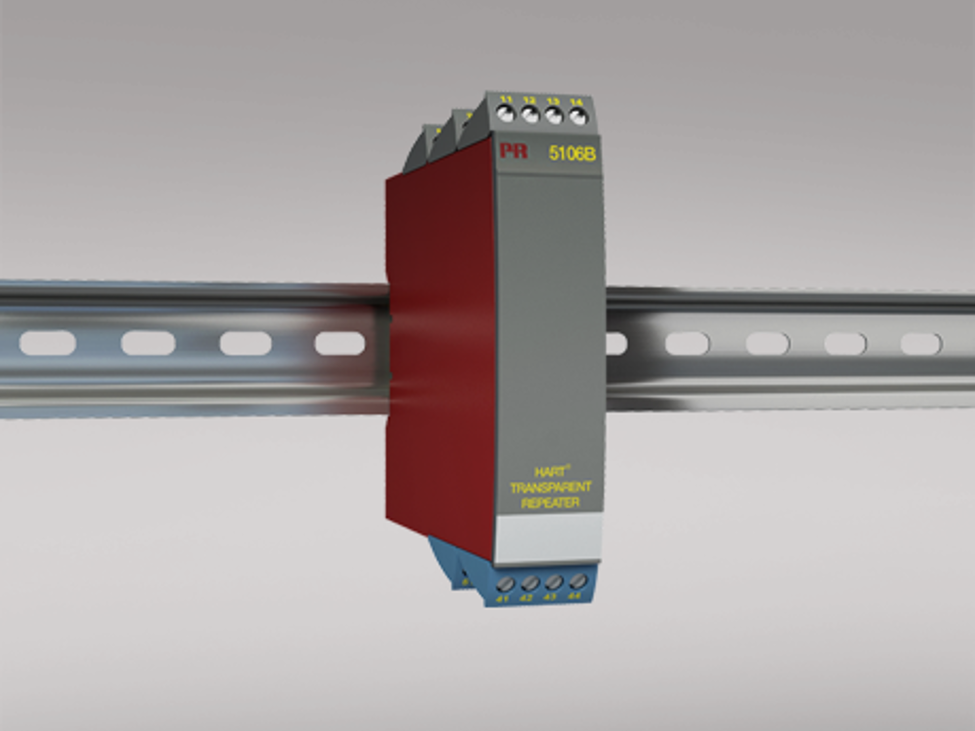
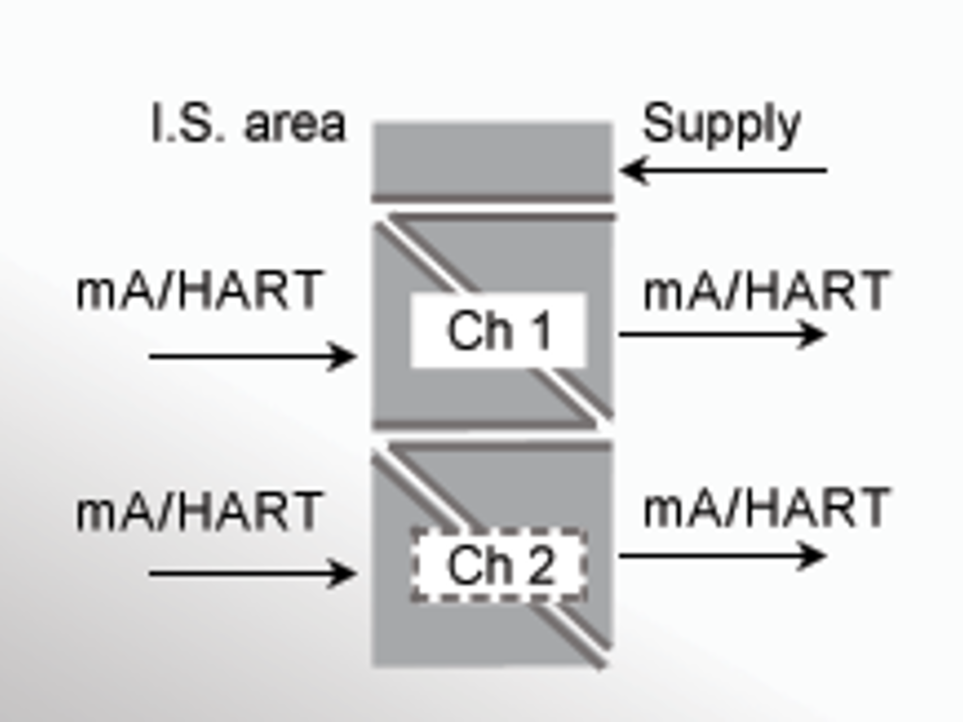
The HART transparent repeater plays a key role in ensuring continuous, accurate signal transmission in hazardous areas. Devices like the PR 9106B HART transparent repeater provide galvanic isolation and an intrinsically safe interface for field devices, while extending the communication range of HART-enabled devices. By isolating temperature sensors or other field devices from the control system, the repeater ensures that external electrical disturbances do not affect signal accuracy, ensuring real-time data integrity in industrial environments.
When combined with intrinsically safe barriers, the HART transparent repeater provides robust protection and ensures compliance with explosion protection standards. These repeaters can be used in environments where failure could lead to catastrophic consequences, offering a critical solution for reliable communication between field devices and central control systems.
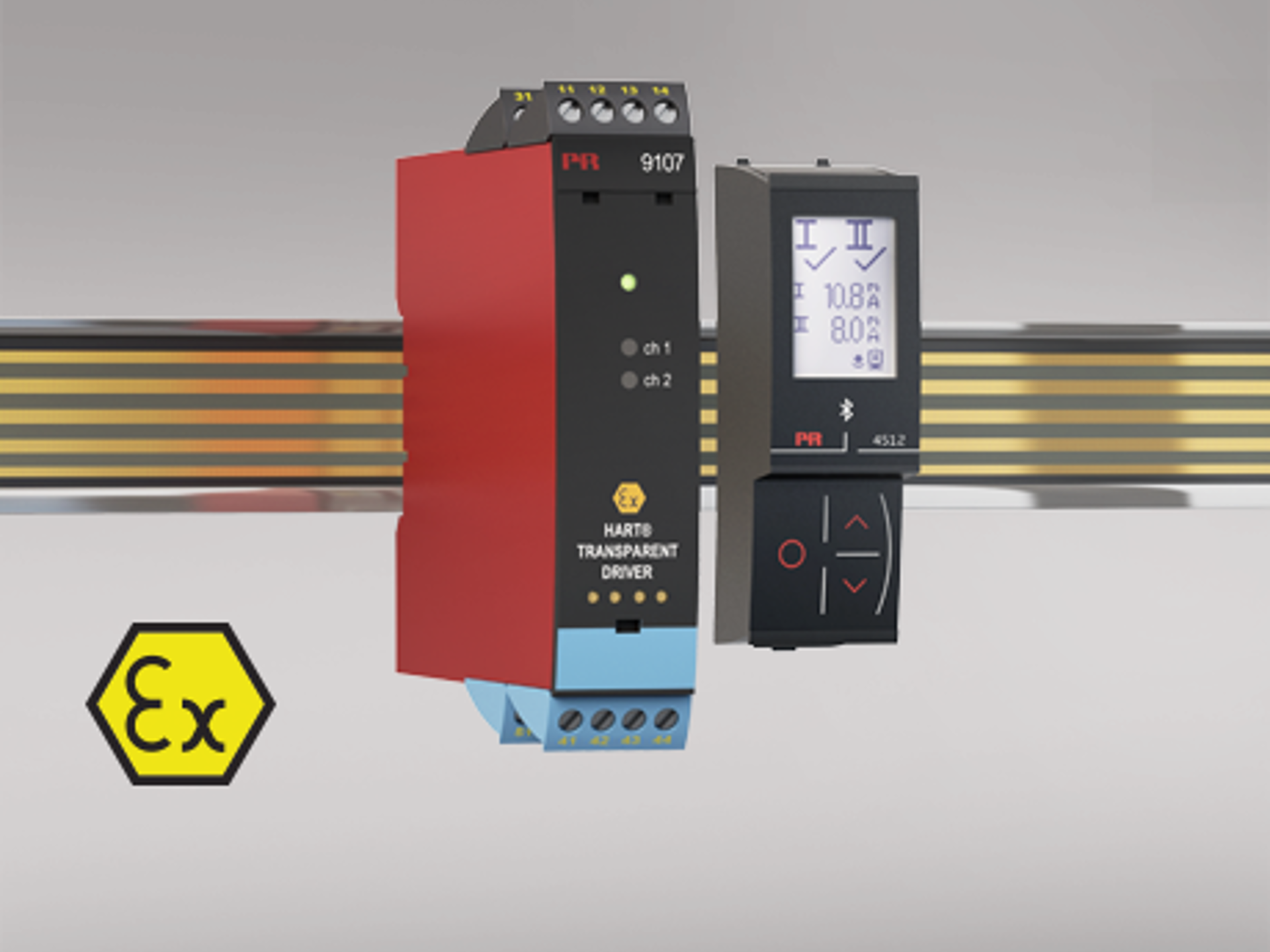
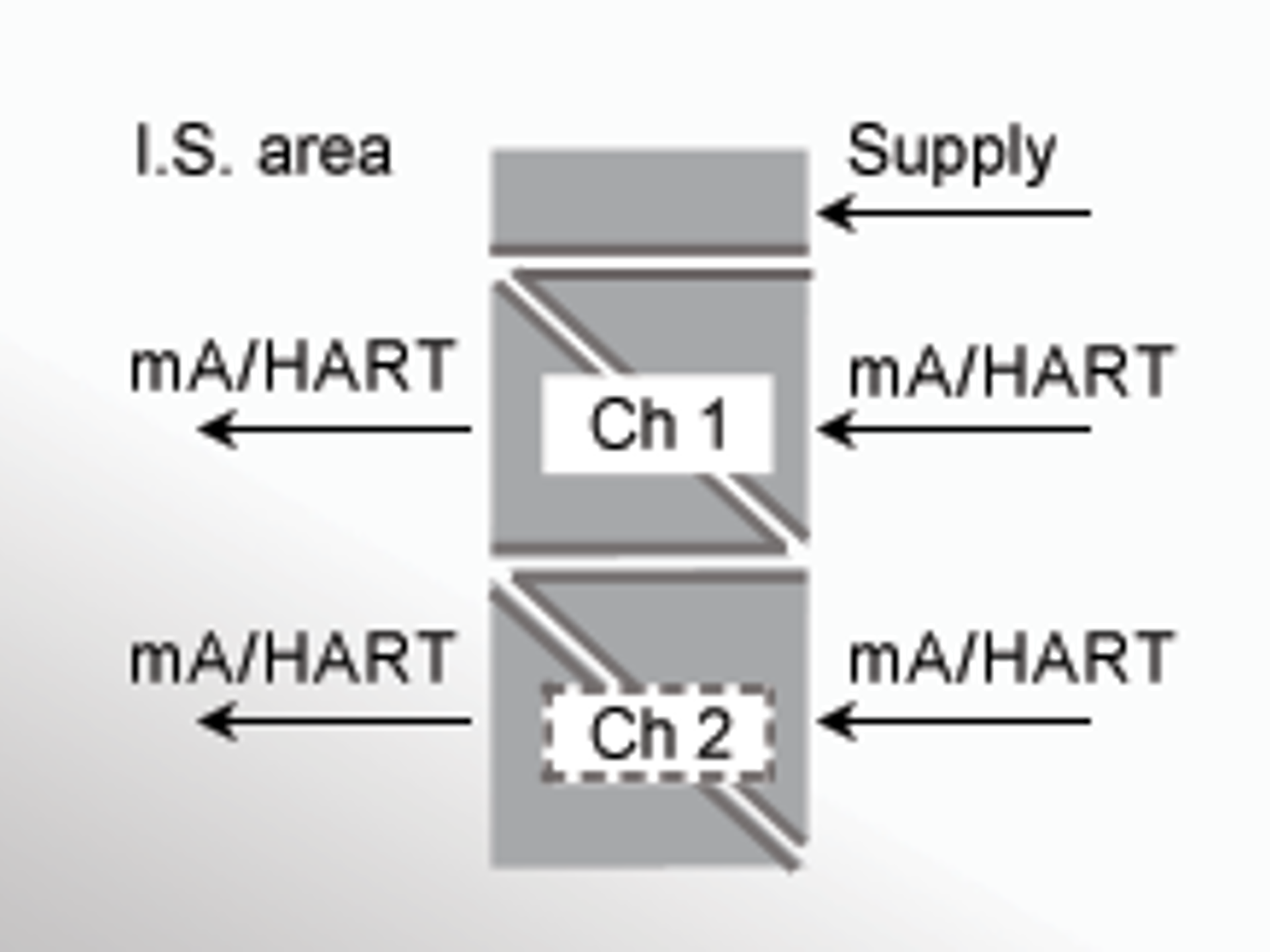
HART Transparent Driver: Powering Devices in Hazardous Environments
The HART transparent driver is designed to power intrinsically safe devices while maintaining safety and operational efficiency. Devices like the PR 9107B HART transparent driver allow for safe signal amplification and bidirectional communication between field devices like i/p actuators, audible alarms, valves, and control lamps, ensuring safe operation in hazardous zones. These drivers provide galvanic isolation to prevent electrical induced disturbances from reaching the connected systems.
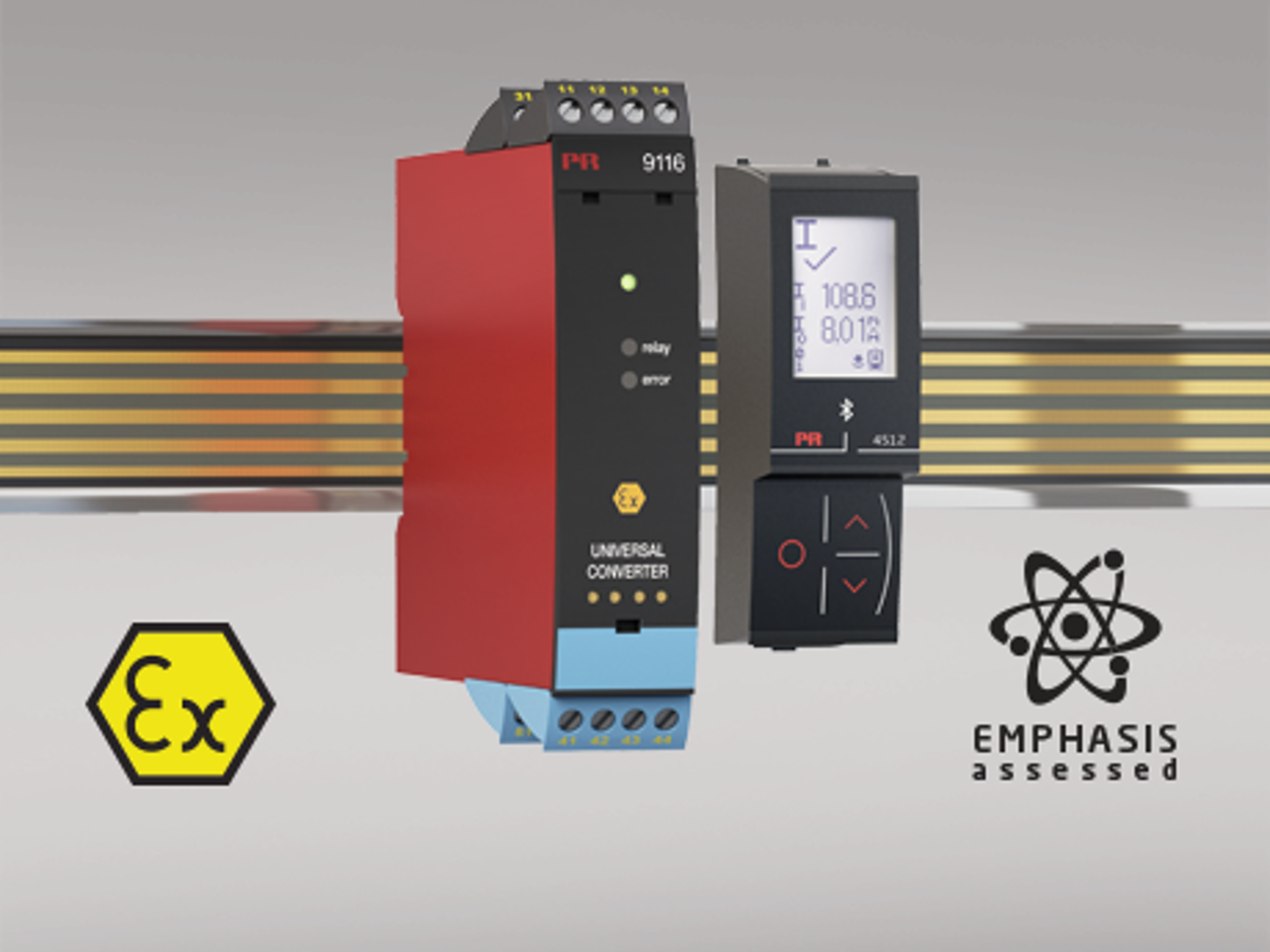
Universal Converter: Flexibility for Different Applications
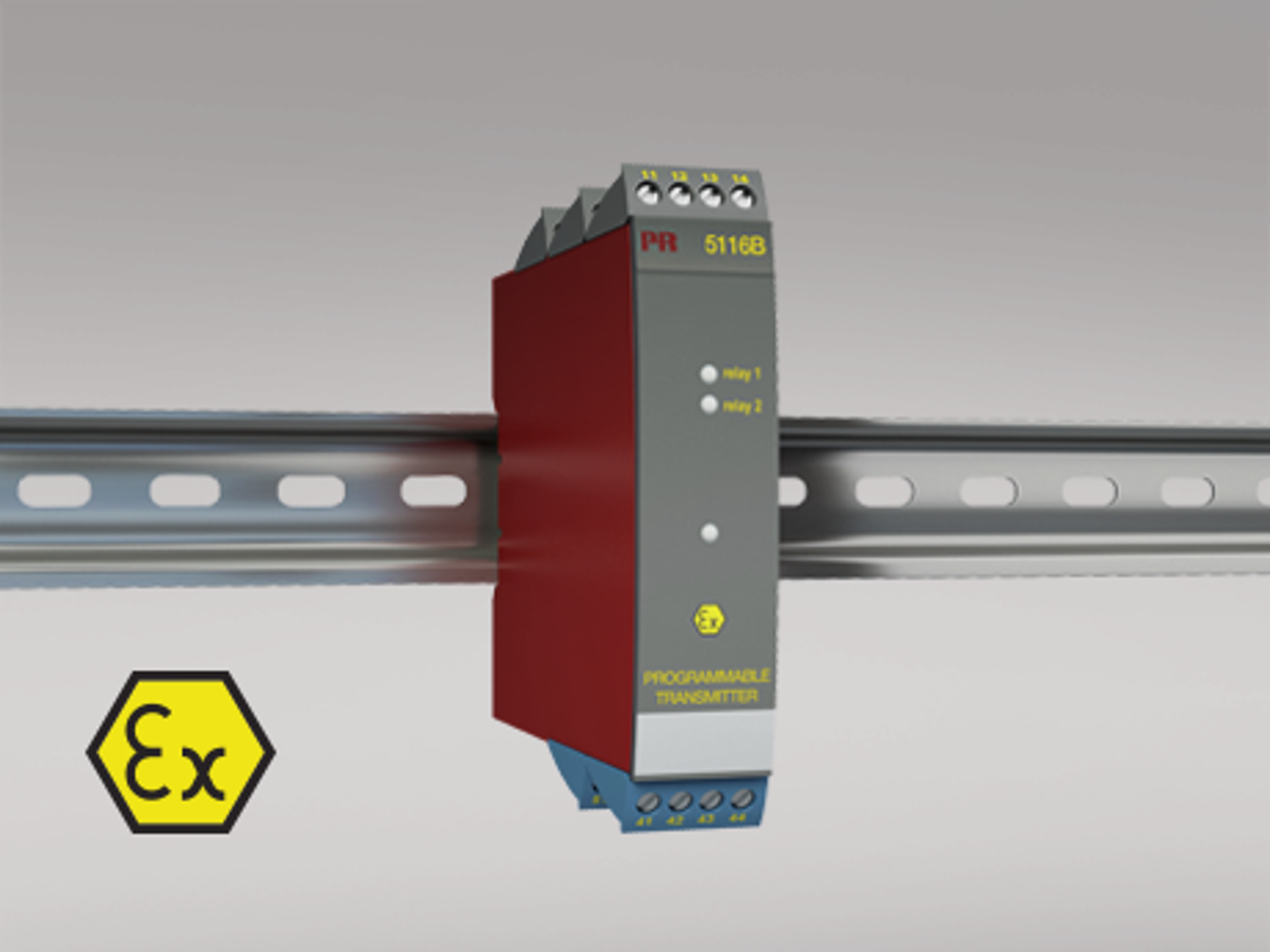
The universal converter like the PR 9116A provides exceptional versatility by supporting a wide range of inputs, including RTD, TC, mV, Ohm, and voltage signals. These devices are especially beneficial in applications where the need for signal isolation and safe energy transmission is critical. The PR 9116A allows for easy integration into various industrial systems, ensuring that signals from field devices are accurately transmitted to control systems in both safe and hazardous environments.
With intrinsically safe barriers integrated into the setup, universal converters help maintain the integrity of measurements and prevent ignition risks in explosive atmospheres, supporting Ex safety standards.
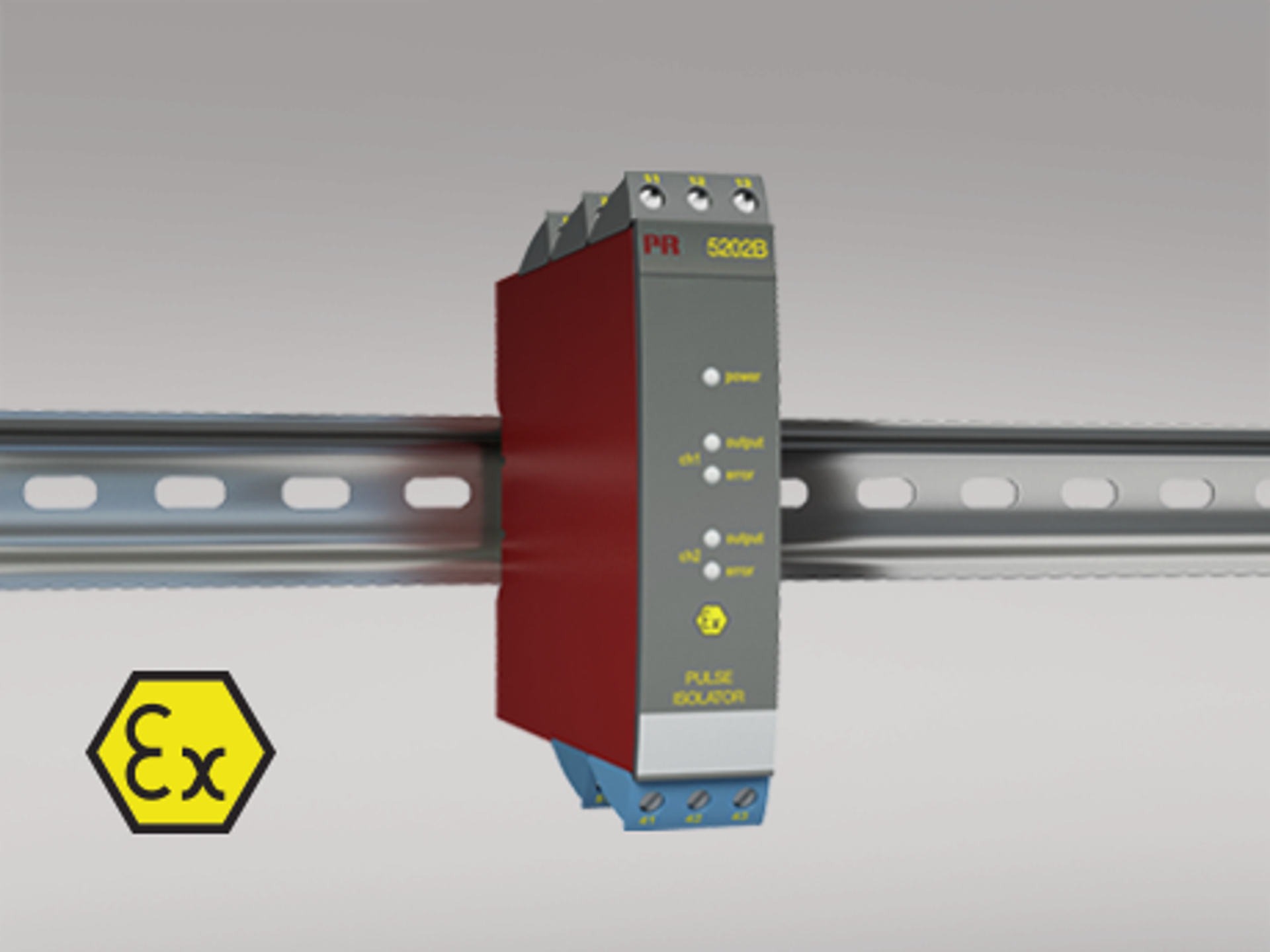
Pulse Isolator / Switch Amplifier: Protecting Signal Integrity
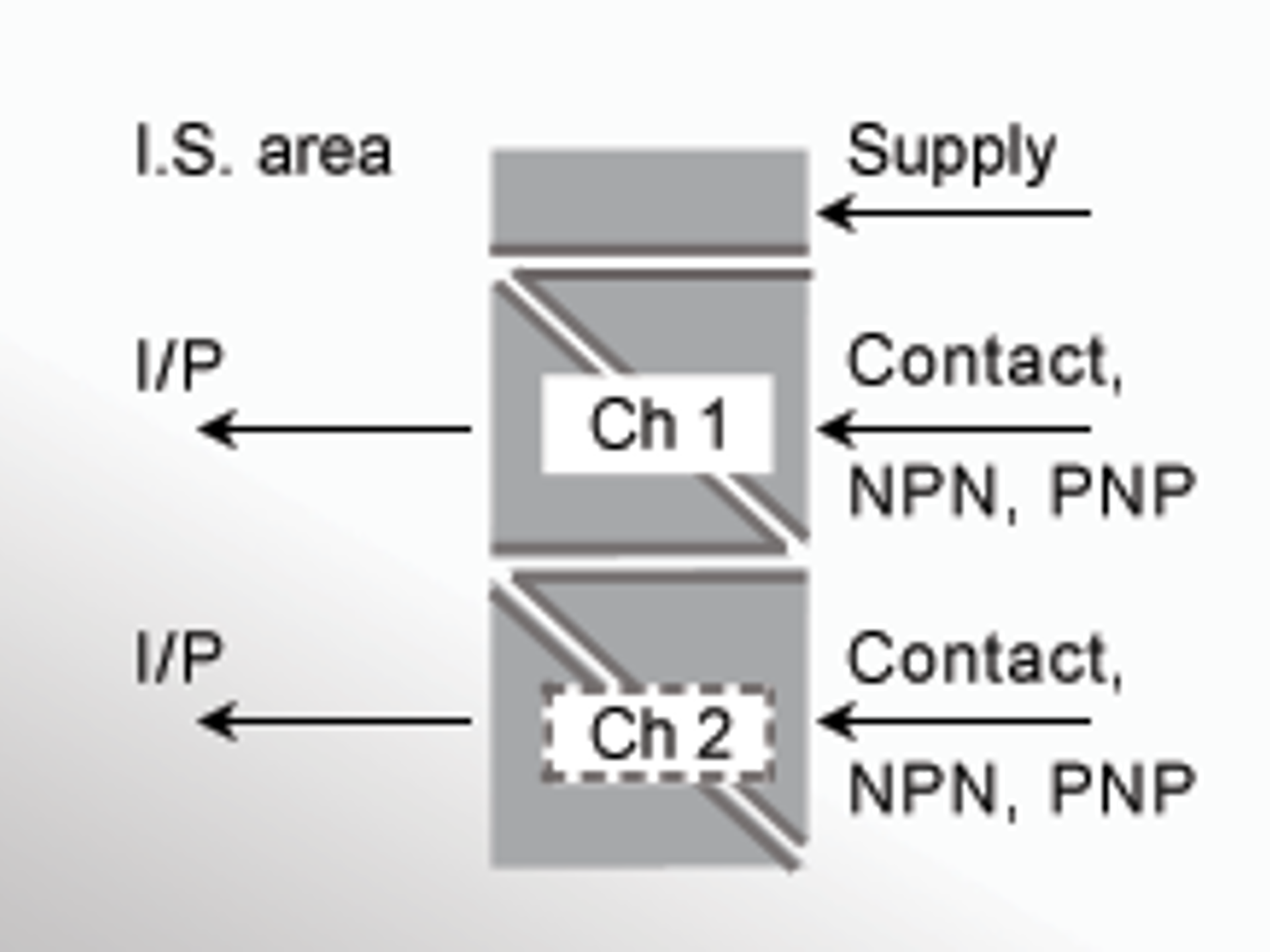
Pulse isolators and switch amplifiers such as the PR 9202B play an essential role in preventing electrical faults from compromising the safety and accuracy of industrial systems. These devices are responsible for ensuring that pulse signals from NAMUR sensors or other devices with a logic output are safely transmitted, even in hazardous areas. They isolate the signals from dangerous electrical transients, ensuring that the control system receives clean data for process control.
When used in conjunction with intrinsically safe barriers, pulse isolators and switch amplifiers provide the necessary protection for systems operating in explosive or hazardous environments. By offering signal isolation and limiting energy levels, they ensure that all systems comply with hazardous areas safety requirements, maintaining operational safety.
Power Supply: Ensuring Safe Energy Delivery
An efficient and safe power supply is essential for industrial systems, especially when operating in hazardous environments. An intrinsically safe power supply like the PR 9421 help ensure that power supplied to devices in hazardous zones remains within safe limits, preventing electrical faults and protecting equipment. By offering galvanic isolation and protection against electrical surges, the PR 9421 ensures continuous and safe energy delivery to connected devices, including transmitters, repeaters and converters.
With the integration of intrinsically safe power supply, industries can ensure that their power supply solutions meet requirements and prevent electrical accidents in explosive environments.
Functional Safety: Meeting SIL Requirements with Intrinsically Safe Barriers
Functional safety is critical in applications where the failure of a system could result in hazardous conditions. Intrinsically safe barriers are key components in maintaining safety in explosive environments, as they limit the energy that can flow into hazardous areas, preventing ignition and ensuring system integrity. Devices like the PR 9106B HART transparent repeater and PR 9107B HART transparent driver work as intrinsically safe barriers to ensure the safe transmission of data and energy in high-risk environments.
Combining the Intrinsic safety with SIL 2/3 certifications and compliance with industry functional safety standards, these solutions provide the highest level of protection for personnel and equipment, ensuring that processes run smoothly and safely.
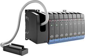 |
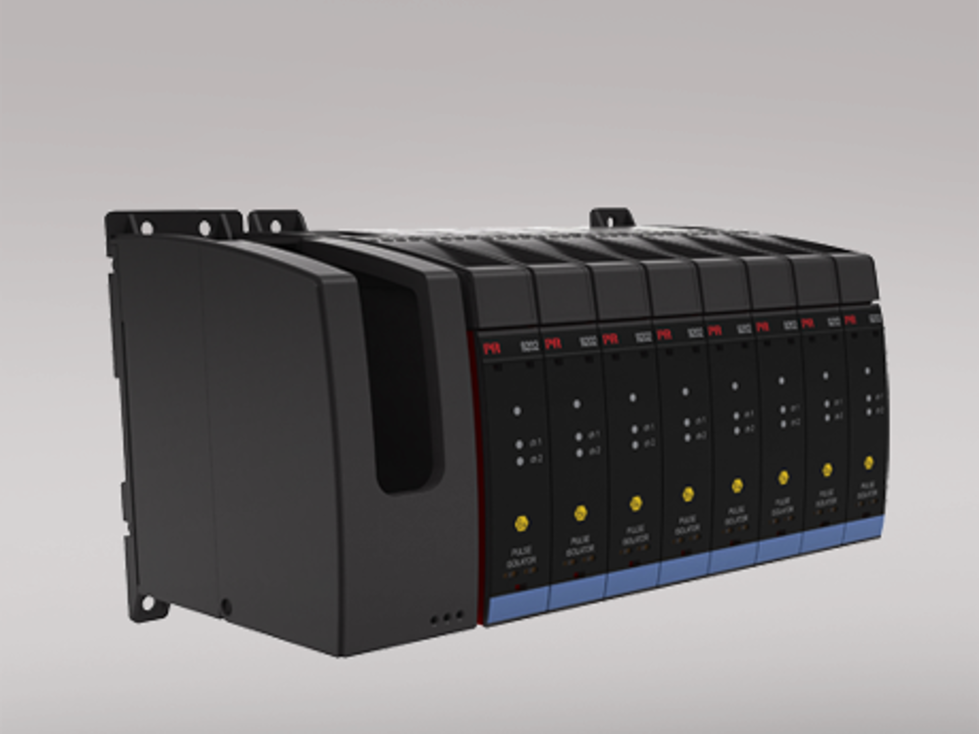
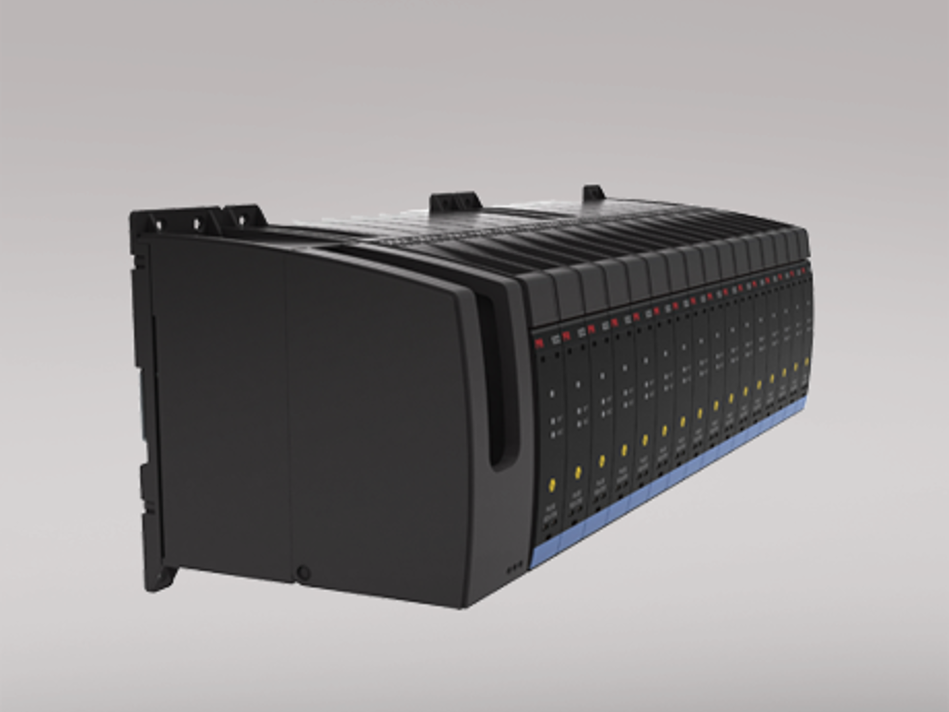
Backplane solutionThe PR9000 series offers unrivalled mounting flexibility. The same device is not only capable of standard DIN rail and Power Rail mounting, but also of being installed in our dedicated backplane solution. For larger installations, the PR backplane greatly simplifies installation and wiring while integrating seamlessly with standard DCS systems.
See backplane selection guide and intro videos
In short - the backplane is a user-friendly and reliable mounting solution between the DCS / PLC / SIS system and isolators / I.S. interfaces |
|
The PR9000 series is fully SIL certified to IEC61508. This allows for easy integration into safety instrumented systems.
Download brochure Get an overview of PR's I.S. range and solutions - download the brochure "Easy to install intrinsically safe solutions with full SIL assessment". |
 |
The PR 9000 series offers you the widest range of multifunctional intrinsic safety interfaces / barriers with the fewest variants. Each product is easy to use and service and, of course, fully SIL compliant. This makes them ideal in more critical industries such as chemical, oil and gas, pharmaceutical and energy. They are intuitive, easy to configure using the detachable communication interfaces.
Achieving Safe, Reliable Industrial Systems with Intrinsically Safe Barriers
Intrinsically safe barriers provide the protection and signal integrity necessary for safe operations in hazardous environments. By integrating signal isolators, temperature converters and universal converters with intrinsically safe barriers, industries can ensure that their systems comply with Explosion protection standards such as EN / IEC 60067. These solutions prevent electrical failures, ensure data accuracy, and enhance the safety of industrial operations, making them indispensable for critical applications in hazardous areas.
Explore our range of intrinsically safe barriers, HART transparent repeaters, and other products designed to improve your system’s safety and performance. At PR electronics, we provide trusted solutions that meet the highest industry standards for safety and reliability.
What to consider: 7 tips and advice for signal conditioning devices in hazardous areas
I.S. specialists are ready to guide you
Need sparring or guidance about signal conditioning in I.S. areas? Don't hesitate to contact us.
What is intrinsic safety (I.S.) and why are I.S. interface barriers necessary in process automation?
Intrinsic safety is an explosion protection method that limits the electrical energy available in a circuit to levels below what could ignite a specific hazardous atmosphere (gas, dust, or fibers). I.S. interface barriers — such as the PR 9106B and PR 9107B — are installed between the safe area (control room) and the hazardous area (field), ensuring that fault conditions cannot deliver sufficient energy to cause ignition. Unlike other protection methods (e.g., flameproof enclosures), intrinsic safety allows live maintenance and diagnostics without hot work permits.
What is the difference between a HART transparent repeater (PR 9106B) and a HART transparent driver (PR 9107B)?
The PR 9106B is a 1:1 isolated repeater that passes both the 4-20 mA analog signal and the superimposed HART/BRAIN digital communication transparently from the hazardous area to the safe area. It supports both active (externally powered) and passive (loop-powered) 2-wire transmitter connections. The PR 9107B is a driver that actively powers field devices from the safe side and transparently passes the HART signal. The 9107B provides up to 725 Ω load at 20 mA output, making it suitable for driving instruments over longer cable runs.
What hazardous area zone classifications are covered by PR electronics I.S. interfaces?
PR electronics I.S. interfaces are approved for use with field devices installed in Zone 0, Zone 1, Zone 2 (gas), and Zone 20, Zone 21, Zone 22 (dust) per ATEX and IECEx standards. For North American installations, they cover Class I/II/III, Division 1 and Division 2, Groups A through G. The interface devices themselves are typically installed in the safe area or in Zone 2/Division 2 locations. This comprehensive zone coverage makes them suitable for the most demanding applications in oil & gas, chemical, and pharmaceutical plants.
What is the galvanic isolation rating of the PR 9106B, and why does it matter?
The PR 9106B provides 2.6 kVAC reinforced galvanic isolation (300 VAC working voltage) between input and output, and 1.5 kVAC (150 VAC working) between the status relay and supply circuits. This high isolation rating prevents ground loops and common-mode voltage interference between the hazardous area field wiring and the safe area control system. In large industrial plants where ground potential differences of tens or even hundreds of volts can exist between remote field instruments and the control room, robust galvanic isolation is essential for measurement integrity.
What is the accuracy and response time of the PR 9106B repeater barrier?
The PR 9106B achieves an overall accuracy better than 0.1% of the selected range, with an absolute mA accuracy of ≤±16 μA and a temperature coefficient of ≤±1.6 μA/°C. The response time is less than 5 ms (0-90%/100-10%), making it fast enough for dynamic process control loops. The supply voltage effect on accuracy is less than ±10 μA, and load stability is ≤0.01% of span per 100 Ω load change. These specifications ensure minimal signal degradation when passing through the barrier.