Loop-powered isolator
6185
- 1-, 2- and 4-channel galvanic isolation
- Slimline channel width of less than 6 mm
- No separate supply necessary
- Low response time
- High noise suppression
Application
- Galvanic separation of analog current signals.
- Elimination of ground loops and measurement of floating signals.
- A competitive choice in terms of both price and technology for galvanic isolation of current signals to SCADA systems or PLC equipment.
- Especially useful in applications necessitating an unproblematic transmission of current signals according to NAMUR (sensor error detection).
Technical characteristics
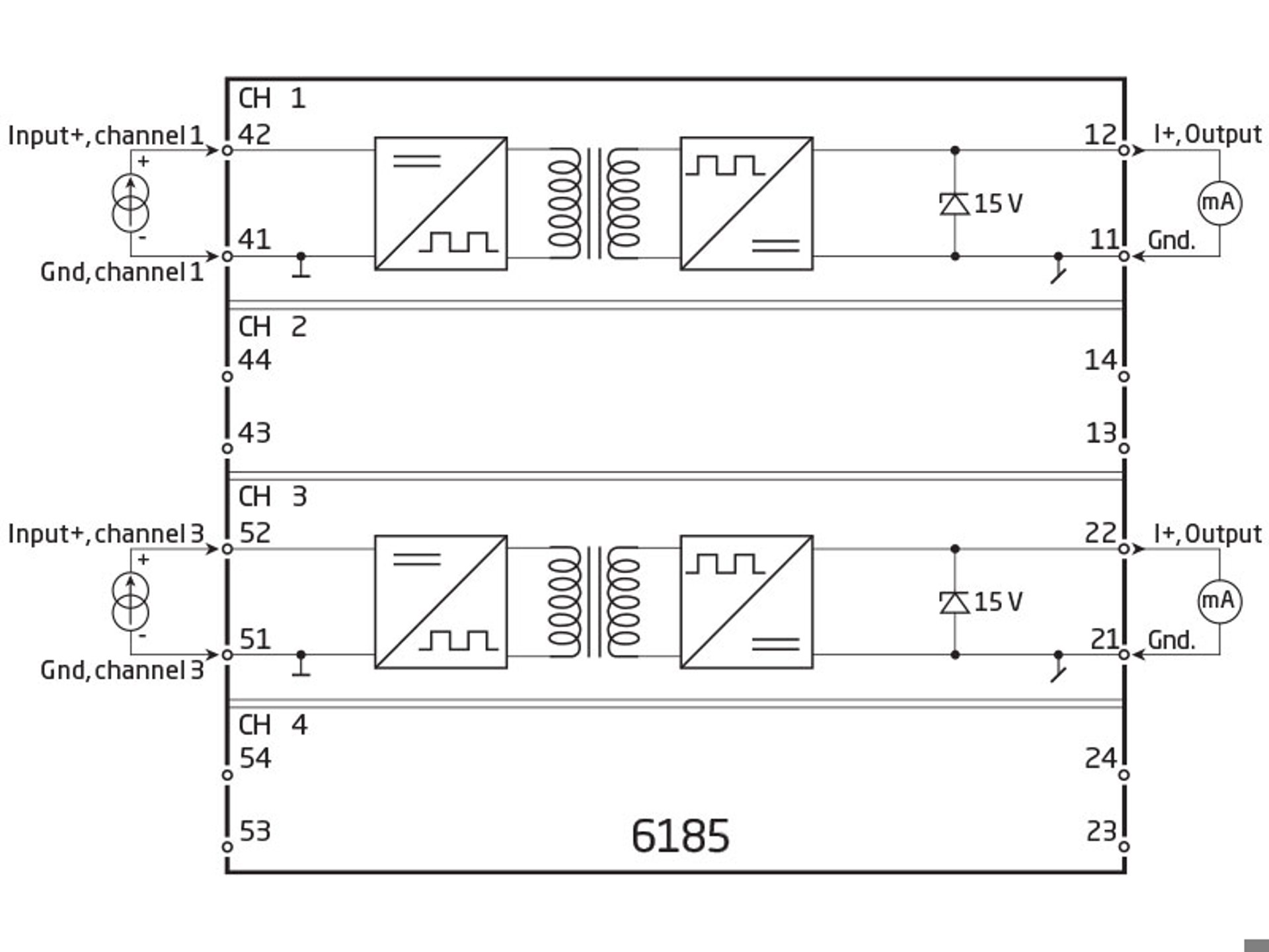
- PR 6185 is powered by the measured signal and loads the loop with max. 1.8 VDC.
- The input is protected against overvoltage and polarity error.
- The drop voltage for each channel can be calculated according to the following expression: Vdrop = 1.8 + (Iout. * Rload.
- The output is voltage-limited to 15 VDC.
- Inputs and outputs are floating and galvanically separated.
Mounting / installation
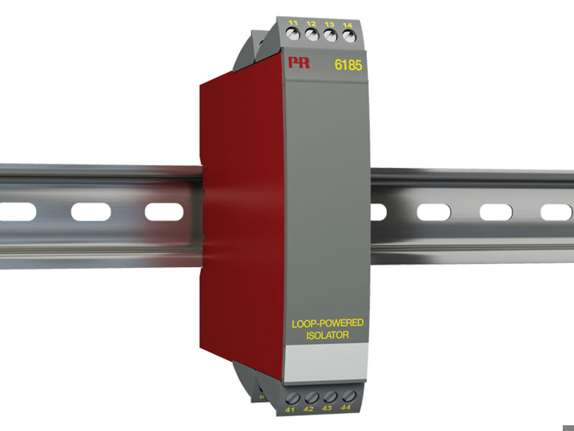
- Mounted vertically or horizontally on a DIN rail. As the devices can be mounted without distance between neighboring units, up to 168 channels can be mounted per meter.
Data sheet & Manuals
Data sheet
- 6185.pdf
- Latest version
Manuals
- 6185V101_UK.pdf
- 6185V100_UK.pdf
- Previous versions
- Latest version
Manuals in Russian
- 6185V101_RU.pdf
- 6185V100_RU.pdf
- Previous versions
- Latest version
Supplementary documentation
EU Declaration of Conformity
- 6185DoC_EU_102_UK.pdf
- 6185DoC_EU_101_UK.pdf
- 6185DoC_EU_100_UK.pdf
- Previous versions
- Latest version
UKCA Declaration of Conformity
- 6185DoC_UKCA_100_UK.pdf
- Latest version
Safety note
Safety note
- SN6185-103-2443.pdf
- SN6185-102-1933.pdf
- SN6185-101-1615.pdf
- SN6100-100-1035.pdf
- Previous versions
- Latest version
Approvals & Certificates
EAC declaration
- EAC-Declaration.pdf
- Latest version
Metrology Pattern Approval (MPA), Russia
- MPA_Russia.pdf
- Latest version
Order form
Environmental Conditions
| Operating temperature | -20°C to +60°C |
| Calibration temperature | 20...28°C |
| Relative humidity | < 95% RH (non-cond.) |
| Protection degree | IP20 |
Mechanical specifications
| Dimensions (HxWxD) | 109 x 23.5 x 104 mm |
| Weight approx. | 155 / 180 / 230 g (1 / 2 / 4 channels) |
| DIN rail type | DIN EN 60715/35 mm |
| Wire size | 0.13...2.08 mm2 AWG 26...14 stranded wire |
| Screw terminal torque | 0.5 Nm |
Common specifications
Supply |
|
| Power dissipation, per channel | 40 mW |
Isolation voltage |
|
| Test voltage | 2 kVAC |
Response time |
|
| Response time (0...90%, 100...10%) | < 4 ms |
| Voltage drop |
< 1.8 VDC, min.
1.8 V + (Iout.*Rload), max. |
| Signal / noise ratio | Min. 60 dB (0...100 kHz) |
| Accuracy | Better than 0.1% of sel. range |
| EMC immunity influence | < ±0.5% of span |
Input specifications
Current input |
|
| Measurement range | 0...23 mA |
| Input resistance | ≈ 90 Ω + Rload (@ 20 mA) |
Output specifications
Current output |
|
| Signal range | 0...23 mA |
| Min. signal range | 1:1 |
| Load (@ current output) | ≤ 600 Ω |
| Load stability | < 0.03% of span / 100 Ω |
| Current limit | 50 mA |
| Voltage limit | 15 VDC |
| of span | = of the presently selected range |
Observed authority requirements
| EMC | 2014/30/EU & UK SI 2016/1091 |
| RoHS | 2011/65/EU & UK SI 2012/3032 |
| EAC | TR-CU 020/2011 |
Need support to select the right product for your application?
Our sales engineers are ready to help specify the right device to meet your needs.
Reach out by phone to get in touch with us straight away – or use the contact form or quick quote function to send your RFQ directly from the website. You’ll get a response within 24 hours on normal business days.
You can expect to get a confirmed delivery date via email within 2 days after we have received your order.
As soon as your package leaves our warehouse, you’ll receive tracking details via email. And if you have any questions along the way we’re just a phone call or email away.
 |
State-of-the-art manufacturing Our 8,500 sqm integrated and automated manufacturing campus in Denmark covers the entire value-chain from design and development to manufacturing. It allows us to design and optimize for testing and manufacturing thereby constantly driving quality up and costs down. |
 |
Dedicated Presale / Aftersales
|
 |
Product reliability |
 |
Product deployment
|
 |
Smart products
Check out our range of communication interfaces
|


