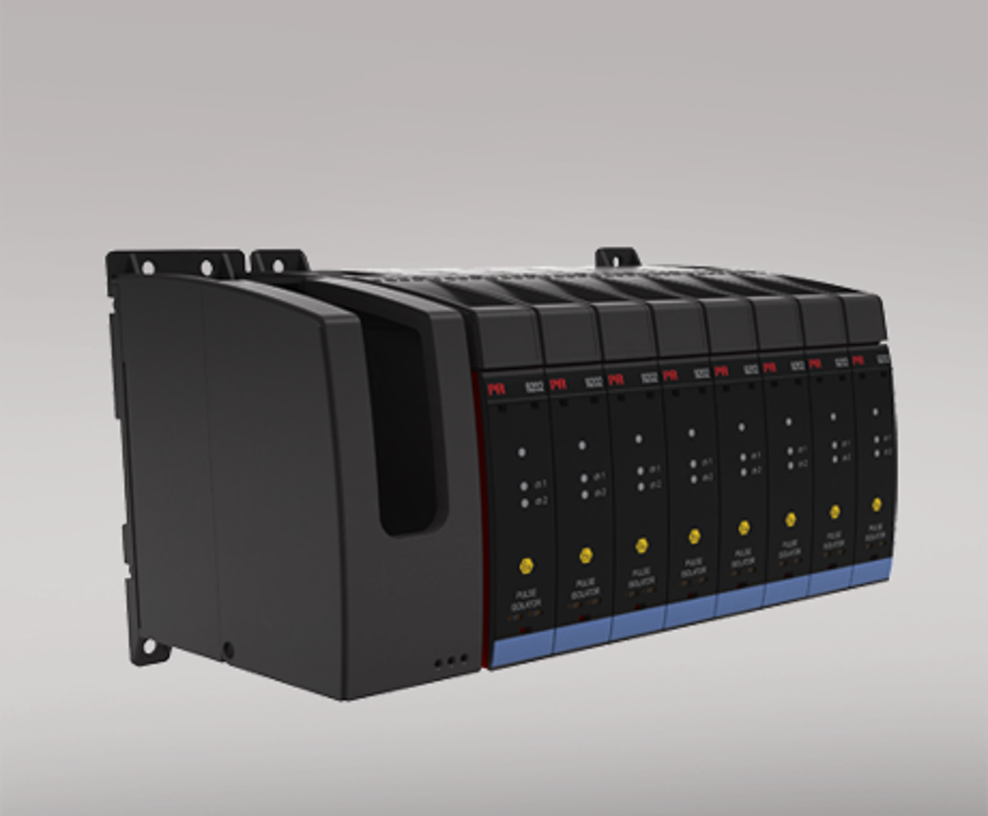
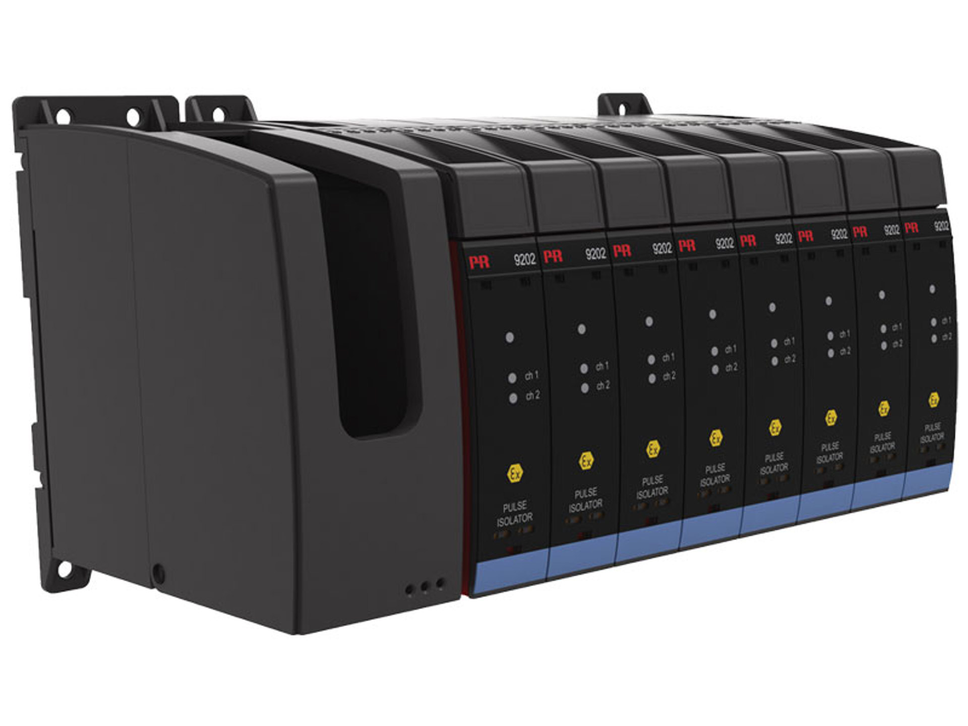
System 9000 backplane
7908
- Provides safe, easy wiring between the backplane and non I.S. automation systems using standard prefabricated I/O cables
- Direct, Redundant and Duplicate signalling - including HART I/O
- Robust, compact high-end design solution for 8 system 9000 units
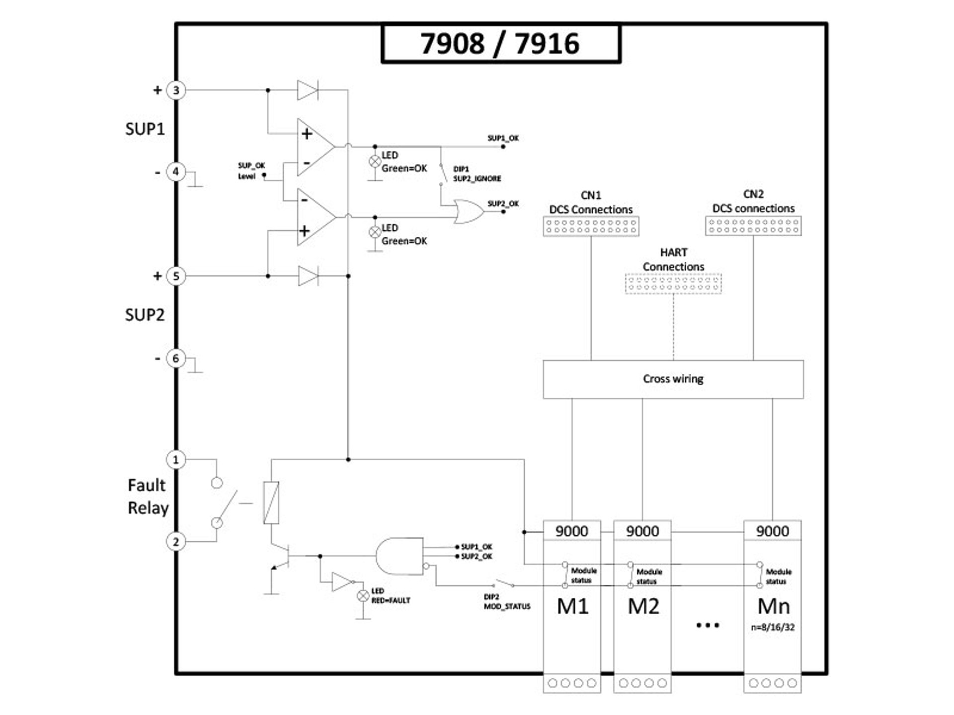
- Digital output and LEDs indicate backplane system status
Application
- The 7908 backplane is a compact and robust solution that enables a safe and easy connection of PR system 9000 IS device signals into standard automation systems.
- Standard automation system cables and connectors are used to link the backplane to the I/O cards.
- The backplane can be used for Direct, Redundant, Duplicate signalling including HART I/O System connectivity (HART MUX).
- The system 9000 devices isolate and convert AI, AO, DI and DO signals coming from, or going to the I.S. classified area, and routes those signals to a system automation I/O card.
- The system 9000 units maintain a SIL2/SIL3 level of functional safety, even when mounted in the backplane solution.
Technical characteristics
- Robust, compact high-end design that holds 8 system 9000 units.
- Digital output indicates status of the 9000 devices and primary/back-up power supplies.
- Flexible 24 VDC supply voltage and redundant power supply connection solution.
Mounting / installation / programming
- Flexible horizontal/vertical panel or wall mounting in the Safe or Zone 2 / Div 2 areas.
- System 9000 devices easily snap ON and OFF using piano keys, and devices can be hot-swapped.
- Tag number and ID labels are easily mounted and read by using the dedicated piano key spacer.
- Wide temperature operation range: -20...+60°C.
- Backplane selection guide can be found at www.prelectronics.com/backplane
Data sheet & Manuals
Data sheet
- 7908.pdf
- Latest version
Manuals
- 7908V102_UK.pdf
- 7908V101_UK.pdf
- 7908V100_UK.pdf
- Previous versions
- Latest version
ABB wiring manual
- 7900AWM102_UK.pdf
- 7900AWM101_UK.pdf
- 7900AWM100_UK.pdf
- Previous versions
- Latest version
Honeywell wiring manual
- 7900HWM102_UK.pdf
- 7900HWM101_UK.pdf
- 7900HWM100_UK.pdf
- Previous versions
- Latest version
Universal wiring manual
- 7900UWM103_UK.pdf
- 7900UWM102_UK.pdf
- 7900UWM101_UK.pdf
- Previous versions
- Latest version
Yokogawa wiring manual
- 7900YWM102_UK.pdf
- 7900YWM101_UK.pdf
- 7900YWM100_UK.pdf
- Previous versions
- Latest version
Approvals & Certificates
ATEX certificate
- 7908_13ATEX0136X_issue2.pdf
- 7908_13ATEX0136X_issue1.pdf
- Previous versions
- Latest version
IECEx certificate
- 7908IEC_130044X_issue1.pdf
- 7908IEC_130044X_issue0.pdf
- Previous versions
- Latest version
FM certificate
- 79xx_FM.pdf
- Latest version
UL certificate
- 7908_16_UL.pdf
- Latest version
EAC declaration
- EAC_EMC_declaration_Ex_3000_5000_6000_9000.pdf
- Latest version
Metrology Pattern Approval (MPA), Russia
- MPA_Russia.pdf
- Latest version
Supplementary documentation
EU Declaration of Conformity
- 7908DoC_EU_103_UK.pdf
- 7908DoC_EU_102_UK.pdf
- 7908DoC_EU_101_UK.pdf
- 7908DoC_EU_100_UK.pdf
- Previous versions
- Latest version
Backplane selection guide
Safety note
Safety note
- SN7900-104-2423.pdf
- SN7900-103-1811.pdf
- SN7900-102-1702.pdf
- SN7900-101-1613.pdf
- SN7900-100-1350.pdf
- Previous versions
- Latest version
Order form
Environmental Conditions
| Operating temperature | -20°C to +60°C |
| Storage temperature | -40°C to +85°C |
| Relative humidity | < 95% RH (non-cond.) |
| Installation in | Pollution degree 2 & meas. / overvoltage cat. II |
Mechanical specifications
| Dimensions (HxWxD) | 144 x 247 x 141 mm |
| Wire size |
2.5 mm2 / AWG 12
(Supply 1 / 2 and status relay connectors) |
Common specifications
Supply |
|
| Supply voltage | 20...31.2 VDC (24 DC nom.) |
| Max. required power | ≤ 30 W |
Isolation voltage |
|
| Isolation voltage, test / working |
500 VAC / 50 VAC
(Basic isolation between supply 1 & 2 and status relay) |
| Replaceable fuses | Fuse F1 & F2: 1.6 A SB, 250 V, type TR5 |
Output specifications
Status relay |
|
| Max. voltage |
32 V (Zone 2 / Div. 2 area)
42 V (Safe area) |
| Max. current |
100 mA (Zone 2 / Div. 2 area)
100 mA (Safe area) |
Observed authority requirements
| EMC | 2014/30/EU |
| EAC | TR-CU 020/2011 |
Approvals
| c UL us, UL 508 | E231911 |
| ATEX | DEKRA 13ATEX0136X |
| IECEx | DEK 13.0044X |
| FM | 0003049918-C |
Need support to select the right product for your application?
Our sales engineers are ready to help specify the right device to meet your needs.
Reach out by phone to get in touch with us straight away – or use the contact form or quick quote function to send your RFQ directly from the website. You’ll get a response within 24 hours on normal business days.
You can expect to get a confirmed delivery date via email within 2 days after we have received your order.
As soon as your package leaves our warehouse, you’ll receive tracking details via email. And if you have any questions along the way we’re just a phone call or email away.
 |
State-of-the-art manufacturing Our 8,500 sqm integrated and automated manufacturing campus in Denmark covers the entire value-chain from design and development to manufacturing. It allows us to design and optimize for testing and manufacturing thereby constantly driving quality up and costs down. |
 |
Dedicated Presale / Aftersales
|
 |
Product reliability |
 |
Product deployment
|
 |
Smart products
Check out our range of communication interfaces
|

