


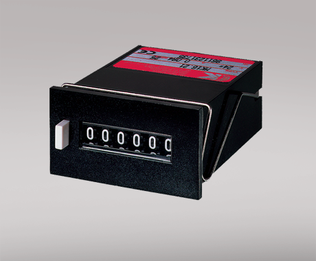
Programmable f/I-f/f converter
PR 5225A
- Pulse conditioning
- Frequency generator
- Concurrent f/I and f/f function
- Analog current and voltage output
- PNP / NPN output, optional relays
- Programmable by PC and Loop Link
Advanced features
- The 5225 transmitter can be configured with a standard PC and the Loop Link communications unit, or delivered fully configured.
Application
- The f/I function performs frequency to current and voltage conversion.
- The f/f function can be used for pulse division or multiplication and as a buffer collecting fast pulse trains.
- The concurrent f/I and f/f functions enable a scaled digital output signal in conjunction with the analog output.
- The frequency generator function is used as e.g. a time base or clock generator.
- Input and supply polarity reversal protection.
- Programmable digital outputs including NPN, PNP or relay options.
Technical characteristics
- 4 front LEDs, indicating f in active inputs (not NPN), Dig.out.1 (NPN or relay 1) and Dig.out 2 (relay 2) outputs, and a NAMUR input error signal.
- Analog current output can be configured to any current within 0...20 mA range.
- Voltage output range is selectable between 0...10 VDC and 0...1 VDC by use of internal jumpers.
- Input range:
Frequency: 0...20,000 Hz
Sensor types: NAMUR, tacho, NPN, PNP, TTL, S0
- Output range:
Current and voltage output: 0...20 mA / 0...10 V
Relay outputs: 0...20 Hz
NPN and PNP output as f/f: 0...1000 Hz
NPN and PNP output as generator: 0...20,000 Hz
Data sheet & Manuals
Data sheet
- 5225A.pdf
- Latest version
Manuals
- 5225V101_UK.pdf
- Latest version
Manuals in Russian
- 5225V101_RU.pdf
- Latest version
Supplementary documentation
EU Declaration of Conformity
- 5225DoC_EU_102_UK.pdf
- 5225DoC_EU_101_UK.pdf
- 5225DoC_EU_100_UK.pdf
- Previous versions
- Latest version
PR default configurations
- PR_default_configurations.pdf
- Latest version
Safety note
Safety note
- SN5000-3-106-2615.pdf
- SN5000-3-105-2605.pdf
- SN5000-3-104-2535.pdf
- SN5000-3-103-1933.pdf
- SN5000-3-102-1613.pdf
- SN5000-101-1450.pdf
- Previous versions
- Latest version
Approvals & Certificates
EAC declaration
- EAC-Declaration.pdf
- Latest version
Metrology Pattern Approval (MPA), Russia
- MPA_Russia.pdf
- Latest version
View variants
Environmental Conditions
| Operating temperature | -20°C to +60°C |
| Calibration temperature | 20...28°C |
| Relative humidity | < 95% RH (non-cond.) |
| Protection degree | IP20 |
Mechanical specifications
| Dimensions (HxWxD) | 109 x 23.5 x 130 mm |
| Weight approx. | 190 g |
| DIN rail type | DIN EN 60715/35 mm |
| Wire size | 0.13...2.08 mm2 AWG 26...14 stranded wire |
| Screw terminal torque | 0.5 Nm |
Common specifications
Supply |
|
| Supply voltage | 19.2...28.8 VDC |
| Max. required power | 3.5 W |
| Internal power dissipation | 1.7 W |
Isolation voltage |
|
| PELV/SELV | IEC 61140 |
| Warm-up time | 30 s |
| Power-up delay | 0...999 s |
| Programming | PR 5909 Loop Link communications interface |
| Signal / noise ratio | Min. 60 dB |
| Response time, analog | < 60 ms + period |
| Response time, digital output | < 50 ms + period |
| Response time, concurrent f/I and f/f | < 80 ms + period |
| Signal dynamics, output | 16 bit |
| Effect of supply voltage change | < ±0.002% of span / %V |
| Auxiliary voltage: NAMUR supply | 8.3 VDC ±0.5 VDC / 8 mA |
| S0 supply | 17 VDC / 20 mA |
| NPN / PNP supply | 17 VDC / 20 mA |
| Special supply (programmable) | 5...17 VDC / 20 mA |
| Temperature coefficient | < ±0.01% of span / °C |
| Linearity error | < 0.1% of span |
| EMC immunity influence | < ±0.5% |
Input specifications
Common input specifications |
|
| Max. offset | 90% of selected max. frequency |
| Measurement range | 0...20 kHz |
| Min. measurement range | 0.001 Hz |
| Low cut-off frequency | 0.001 Hz |
| Max. frequency, with input filter ON | 50 Hz |
| Min. period time with input filter ON | 20 ms |
| Input types |
NAMUR acc. to DIN 19234
Tacho NPN / PNP TTL S0 acc. to DIN 43864 |
Output specifications
Common output specifications |
|
| Updating time |
40 ms for concurrent f/I and f/f
20 ms |
Current output |
|
| Signal range | 0...20 mA |
| Min. signal range | 5 mA |
| Load (@ current output) | ≤ 600 Ω |
| Load stability | ≤ 0.01% of span / 100 Ω |
| Current limit | < 23 mA |
Voltage output |
|
| Signal range | 0...10 VDC |
| Min. signal range | 250 mV |
| Load (@ voltage output) | ≥ 500 kΩ |
Relay output |
|
| Max. switching frequency | 20 Hz |
| Isolation, test / working | 3.75 kVAC / 250 VAC |
| Max. voltage | 250 VRMS |
| Max. current | 2 AAC |
| Max. AC power | 500 VA |
| Max. load at 24 VDC | 1 A |
| Other output types |
Active outputs (NPN / PNP)
f/f converter output Frequency generator |
| of span | = of the presently selected range |
Observed authority requirements
| EMC | 2014/30/EU |
| LVD | 2014/35/EU |
| RoHS | 2011/65/EU |
| EAC | TR-CU 020/2011 |


Do you need help choosing the right device?Our sales engineers are ready to guide you to the device that best fits your application. How to contact us?You can use our quote function or contact form with no obligation. With the quote function, you simply add the devices you are interested in and receive a quote. We will get back to you within 24 hours on business days.
After you orderWhen your order is placed, you will receive a confirmed delivery date within two business days. As soon as your package has been shipped, you will receive an email with tracking details, so you always know where your delivery is. |
 |
State-of-the-art manufacturing Our 8,500 sqm integrated and automated manufacturing campus in Denmark covers the entire value-chain from design and development to manufacturing. It allows us to design and optimize for testing and manufacturing thereby constantly driving quality up and costs down. |
 |
Dedicated Presale / Aftersales
|
 |
Product reliability |
 |
Product deployment
|
 |
Smart products |