
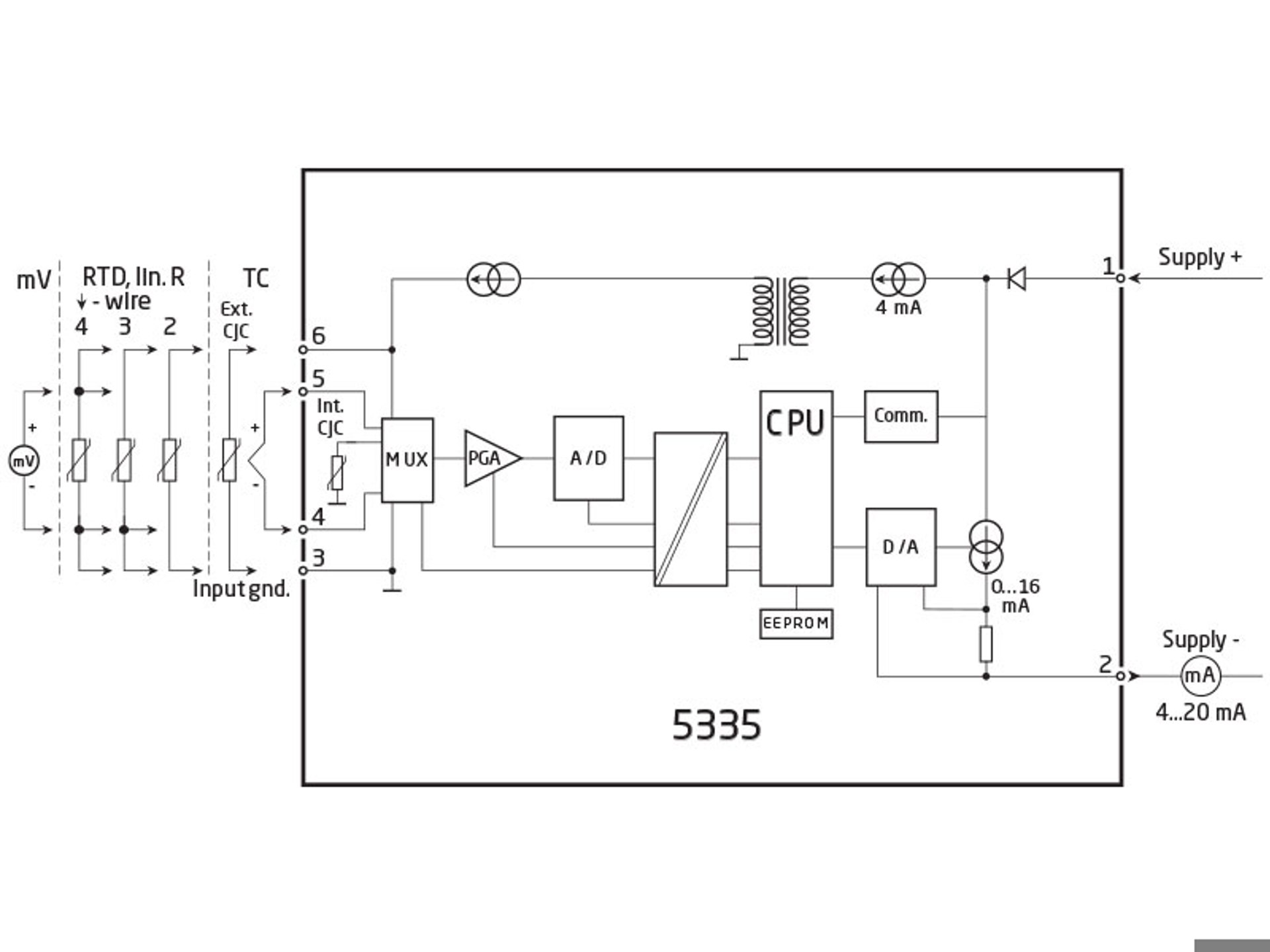
2-wire transmitter with HART protocol
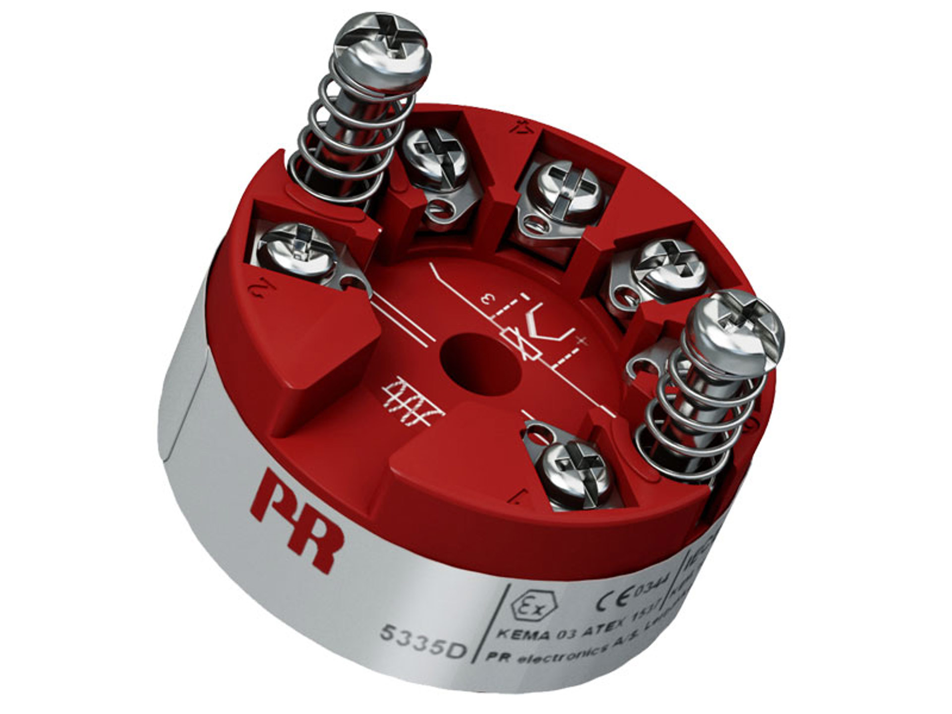
5335D
- RTD, TC, Ohm, or mV input
- Extremely high measurement accuracy
- HART 5 protocol
- Galvanic isolation
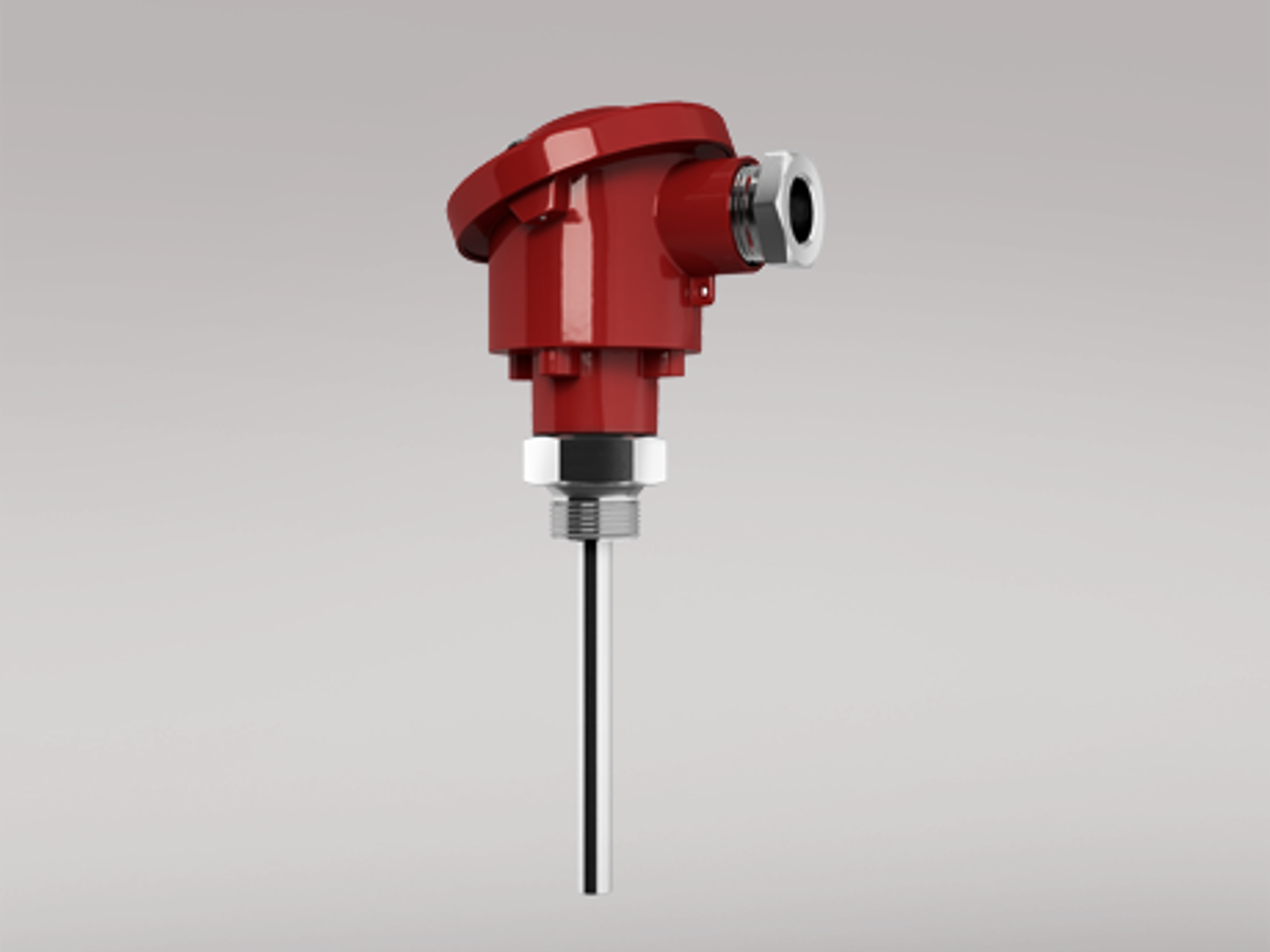
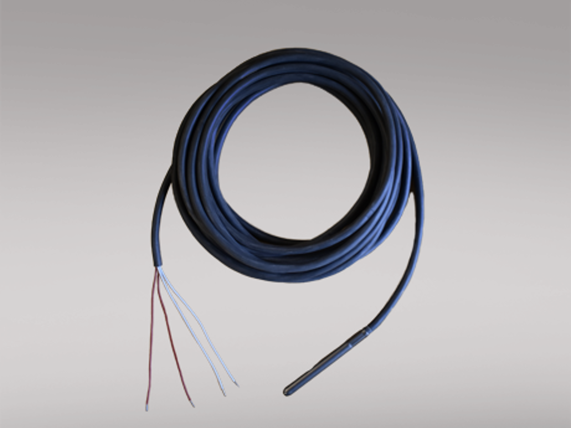
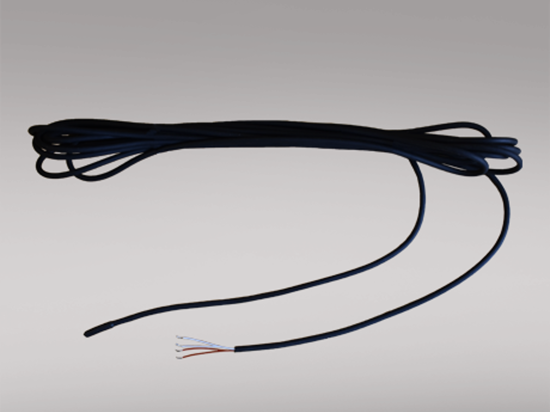
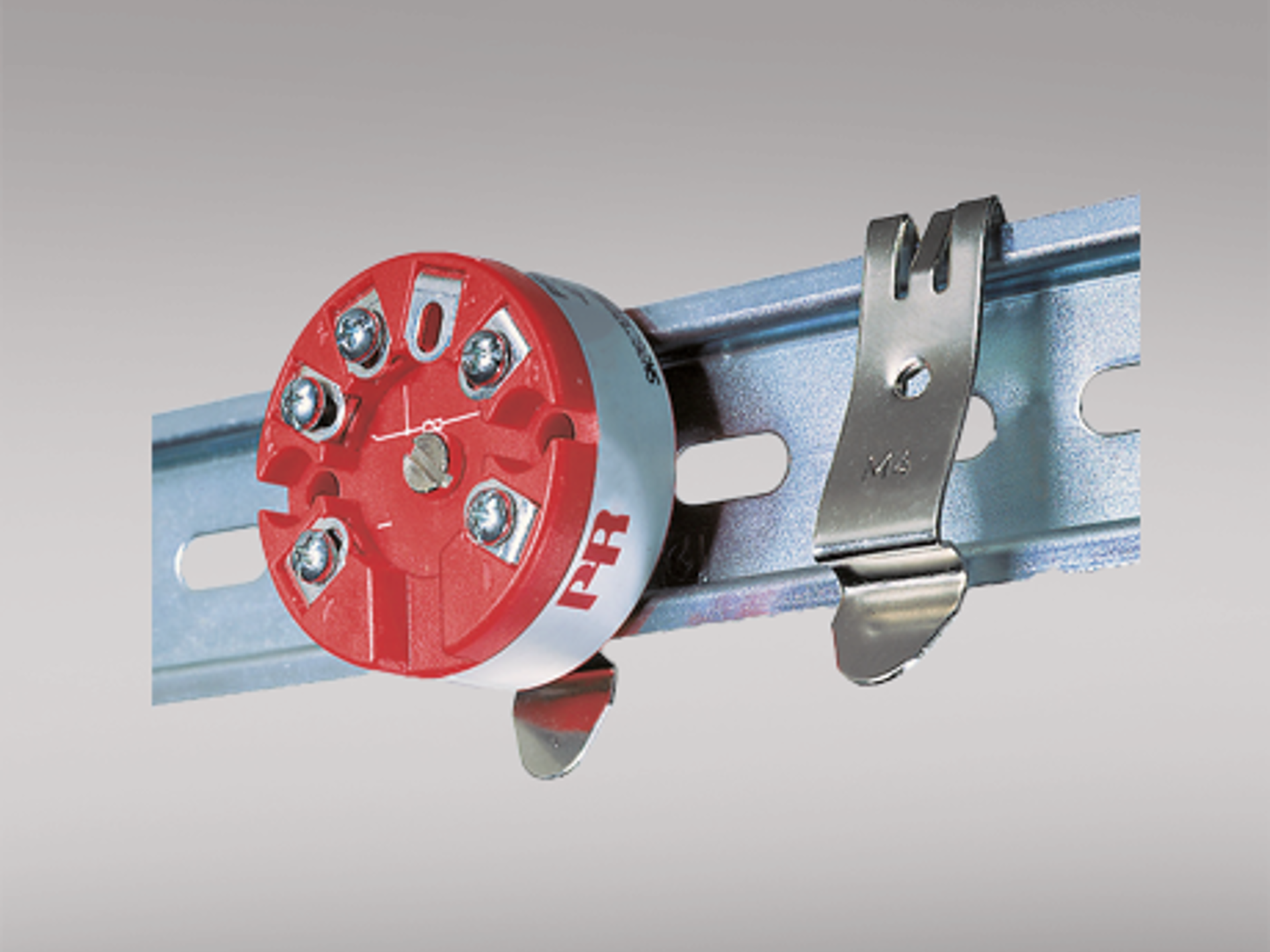
- For DIN form B sensor head mounting
Application
- Linearized temperature measurement with Pt100...Pt1000, Ni100...Ni1000, or TC sensor.
- Difference or average temperature measurement of 2 resistance or TC sensors.
- Conversion of linear resistance variation to a standard analog current signal, for instance from valves or Ohmic level sensors.
- Amplification of a bipolar mV signal to a standard 4...20 mA current signal.
- Connection of up to 15 transmitters to a digital 2-wire signal with HART communication.
Technical characteristics
- Within a few seconds the user can program PR5335D to measure temperatures within all ranges defined by the norms.
- The RTD and resistance inputs have cable compensation for 2-, 3- and 4-wire connection.
- The 5335D provides the required failure data (SFF and PFDAVG) for SIL 2 applications as per IEC 61508 / IEC 61511.
- Continuous check of vital stored data for safety reasons.
- Sensor error detection according to the guidelines in NAMUR NE89.
Mounting / installation
- For DIN form B sensor head mounting.
Data sheet & Manuals
Data sheet
- 5335D.pdf
- Latest version
Manuals
- 5335V123_UK.pdf
- 5335V122_UK.pdf
- 5335V121_UK.pdf
- 5335V120_UK.pdf
- 5335V119_UK.pdf
- 5335V118_UK.pdf
- 5335V117_UK.pdf
- 5335V116_UK.pdf
- 5335V115_UK.pdf
- 5335V114_UK.pdf
- 5335V113.pdf
- 5335V112.pdf
- 5335V111.pdf
- 5335V110.pdf
- 5335V109.pdf
- 5335V108.pdf
- 5335V107.pdf
- Previous versions
- Latest version
Manuals in Russian
Approvals & Certificates
ATEX certificate
- 5335D_20ATEX0108X_issue0.pdf
- 5335D_03ATEX1537_issue11.pdf
- 5335D_03ATEX1537_issue10.pdf
- 5335D_03ATEX1537_issue09.pdf
- 5335D_03ATEX1537_issue08.pdf
- 5335D_03ATEX1537_issue07.pdf
- 5335D_03ATEX1537_issue06.pdf
- Previous versions
- Latest version
IECEx certificate
- 5335DIEC_200063X_issue0.pdf
- 5335DIEC_100083X_issue04.pdf
- 5335DIEC_100083X_issue03.pdf
- Previous versions
- Latest version
CSA certificate
- 533x_633x_CSA.pdf
- Latest version
FM certificate
- 53xx_633x_FM17US0013X.pdf
- 53xx_633x_FM_2D5A7.pdf
- Previous versions
- Latest version
INMETRO certificate
- INMETRO_5335_5337_6335_6337_230011X_issue0.pdf
- INMETRO_5335_5337_180002X_issue1.pdf
- INMETRO_5335_5337_180002X_issue0.pdf
- Previous versions
- Latest version
DNV marine certificate
- DNV_2231_41xx_51xx_53xx.pdf
- Latest version
EAC declaration
- EAC_EMC_declaration_Ex_3000_5000_6000_9000.pdf
- Latest version
EAC Ex certificate
- EAC_Ex.pdf
- Latest version
Metrology Pattern Approval (MPA), Belarus
- MPA_Belarus.pdf
- Latest version
Metrology Pattern Approval (MPA), Kazakhstan
- MPA_Kazakhstan.pdf
- Latest version
Metrology Pattern Approval (MPA), Russia
- MPA_Russia.pdf
- Latest version
Supplementary documentation
EU Declaration of Conformity
- 5335DoC_EU_106_UK.pdf
- 5335DoC_EU_105_UK.pdf
- 5335DoC_EU_104_UK.pdf
- 5335DoC_EU_103_UK.pdf
- 5335DoC_EU_102_UK.pdf
- 5335DoC_EU_101_UK.pdf
- 5335DoC_EU_100_UK.pdf
- 5335DoC_EU_02000.pdf
- 5335DoC_EU_01997.pdf
- Previous versions
- Latest version
UKCA Declaration of Conformity
- 5335DoC_UKCA_100_UK.pdf
- Latest version
CCC statement
- 5000_6000_series_CCC_statement.pdf
- Latest version
FMEDA report
- PR_5335_R026_V3R2.pdf
- Latest version
SIL declaration
- 5335_6335_5337_6337_7501_SIL1_declaration_Potmeter_V2.pdf
- 5335_6335_5337_6337_7501_SIL2_declaration_V2.pdf
HART certificate
- 7501_HART_5_certificate.pdf
- Latest version
PR default configurations
- PR_default_configurations.pdf
- Latest version
Safety note
Order form
Environmental Conditions
| Operating temperature | -40°C to +85°C |
| Calibration temperature | 20...28°C |
| Relative humidity | < 95% RH (non-cond.) |
| Protection degree (encl./terminal) | IP68 / IP00 |
Mechanical specifications
| Dimensions | Ø 44 x 20.2 mm |
| Weight approx. | 50 g |
| Wire size | 1 x 1.5 mm2 stranded wire |
| Screw terminal torque | 0.4 Nm |
| Vibration | IEC 60068-2-6 |
| 2...25 Hz | ±1.6 mm |
| 25...100 Hz | ±4 g |
Common specifications
Supply |
|
| Supply voltage | 8.0...30 VDC |
Isolation voltage |
|
| Isolation voltage, test / working | 1.5 kVAC / 50 VAC |
Response time |
|
| Response time (programmable) | 1...60 s |
| Warm-up time | 30 s |
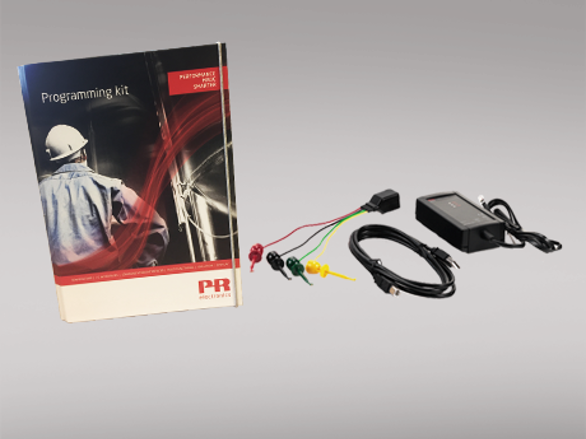
| Programming | Loop Link & HART |
| Signal / noise ratio | > 60 dB |
| Accuracy | Better than 0.05% of selected range |
| Signal dynamics, input | 22 bit |
| Signal dynamics, output | 16 bit |
| Effect of supply voltage change | < 0.005% of span / VDC |
| EMC immunity influence | < ±0.1% of span |
| Extended EMC immunity: NAMUR NE21, A criterion, burst | < ±1% of span |
Input specifications
Common input specifications |
|
| Max. offset | 50% of selected max. value |
RTD input |
|
| RTD type | Pt100, Ni100, lin. R |
| Cable resistance per wire | 5 Ω (up to 50 Ω per wire is possible with reduced measurement accuracy) |
| Sensor current | Nom. 0.2 mA |
| Effect of sensor cable resistance (3-/4-wire) | < 0.002 Ω / Ω |
| Sensor error detection | Yes |
TC input |
|
| Thermocouple type | B, E, J, K, L, N, R, S, T, U, W3, W5 |
| Cold junction compensation (CJC) | < ±1.0°C |
| Sensor error detection | Yes |
| Sensor error current: When detecting / else | Nom. 33 μA / 0 μA |
Voltage input |
|
| Measurement range | -800...+800 mV |
| Min. measurement range (span) | 2.5 mV |
| Input resistance | 10 MΩ |
Output specifications
Current output |
|
| Signal range | 4…20 mA |
| Min. signal range | 16 mA |
| Load (@ current output) | ≤ (Vsupply - 8) / 0.023 [Ω] |
| Load stability | ≤ 0.01% of span / 100 Ω |
| Sensor error indication | Programmable 3.5…23 mA |
| NAMUR NE43 Upscale/Downscale | 23 mA / 3.5 mA |
| of span | = of the presently selected range |
I.S. / Ex marking
| ATEX | II 1 G Ex ia IIC T6...T4 Ga, II 2 D Ex ia IIIC Db, I M1 Ex ia I Ma |
| IECEx | Ex ia IIC T6...T4 Ga, Ex ia IIIC Db, Ex ia I Ma |
| FM, US | Cl. I, Div. 1, Gp. A, B, C, D T4/T6; Cl. I Zone 0, AEx ia IIC T4/T6; Cl. 1, Div. 2, Gp. A, B, C, D, T4/T6 |
| CSA | Cl. I, Div. 1, Gp. A, B, C, D Ex ia IIC, Ga |
| INMETRO | Ex ia IIC T6...T4 Ga, Ex ia IIIC Db, Ex ia I Ma |
Observed authority requirements
| EMC | 2014/30/EU & UK SI 2016/1091 |
| ATEX | 2014/34/EU & UK SI 2016/1107 |
| RoHS | 2011/65/EU & UK SI 2012/3032 |
| EAC | TR-CU 020/2011 |
| EAC Ex | TR-CU 012/2011 |
Approvals
| ATEX | DEKRA 20ATEX0108X |
| IECEx | DEK 20.0063X |
| FM | FM17US0013X |
| CSA | 1125003 |
| INMETRO | DEKRA 23.0011X |
| DNV Marine | TAA0000101 |
| EAC Ex | EAEU KZ 7500361.01.01.08756 |
| SIL | Hardware assessed for use in SIL applications |


Need support to select the right product for your application?
Our sales engineers are ready to help specify the right device to meet your needs.
Reach out by phone to get in touch with us straight away – or use the contact form or quick quote function to send your RFQ directly from the website. You’ll get a response within 24 hours on normal business days.
You can expect to get a confirmed delivery date via email within 2 days after we have received your order.
As soon as your package leaves our warehouse, you’ll receive tracking details via email. And if you have any questions along the way we’re just a phone call or email away.
 |
State-of-the-art manufacturing Our 8,500 sqm integrated and automated manufacturing campus in Denmark covers the entire value-chain from design and development to manufacturing. It allows us to design and optimize for testing and manufacturing thereby constantly driving quality up and costs down. |
 |
Dedicated Presale / Aftersales
|
 |
Product reliability |
 |
Product deployment
|
 |
Smart products
Check out our range of communication interfaces
|
