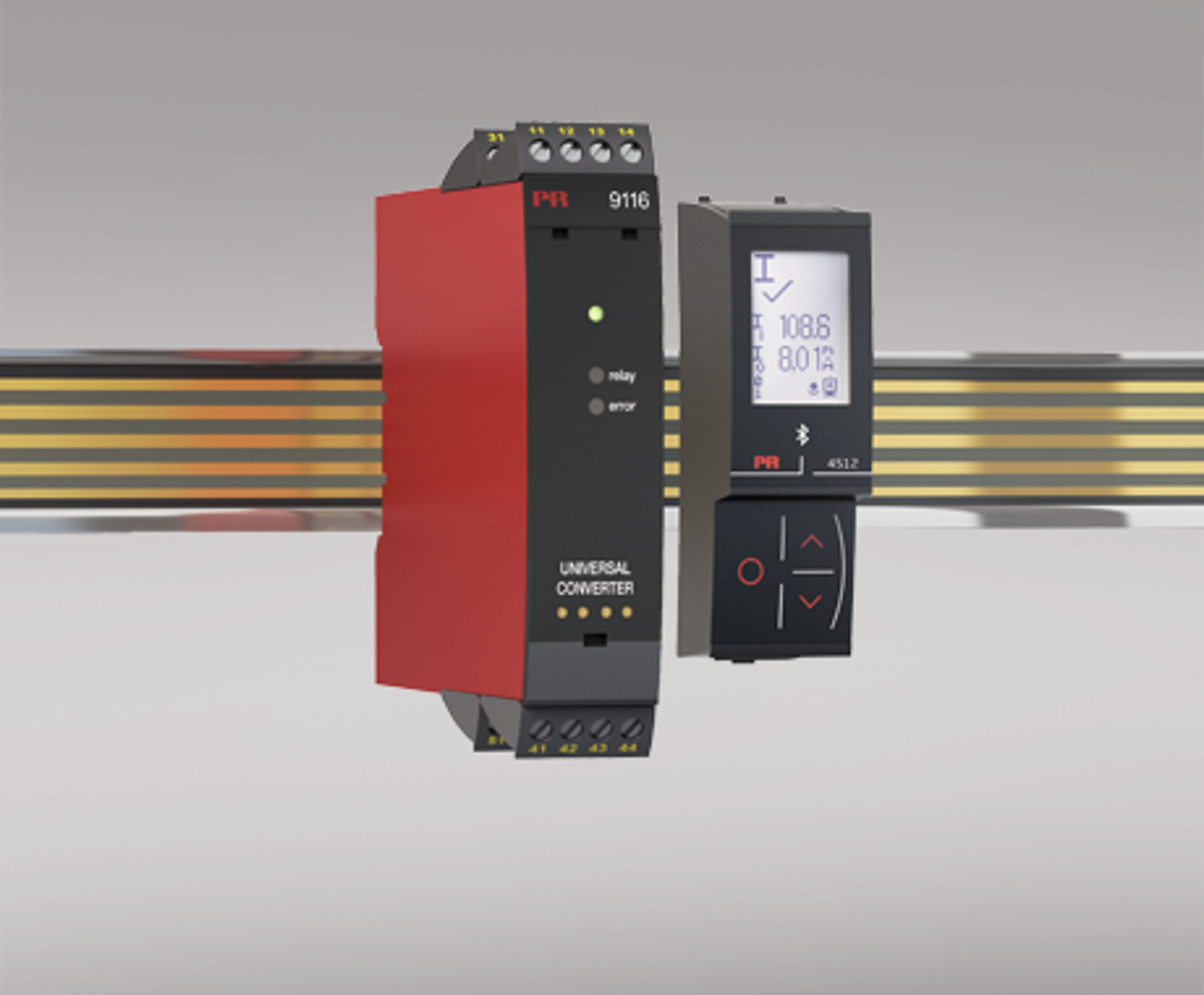
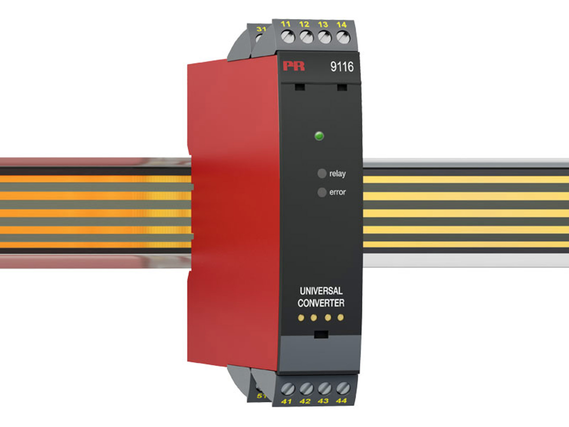

Universal converter
9116A
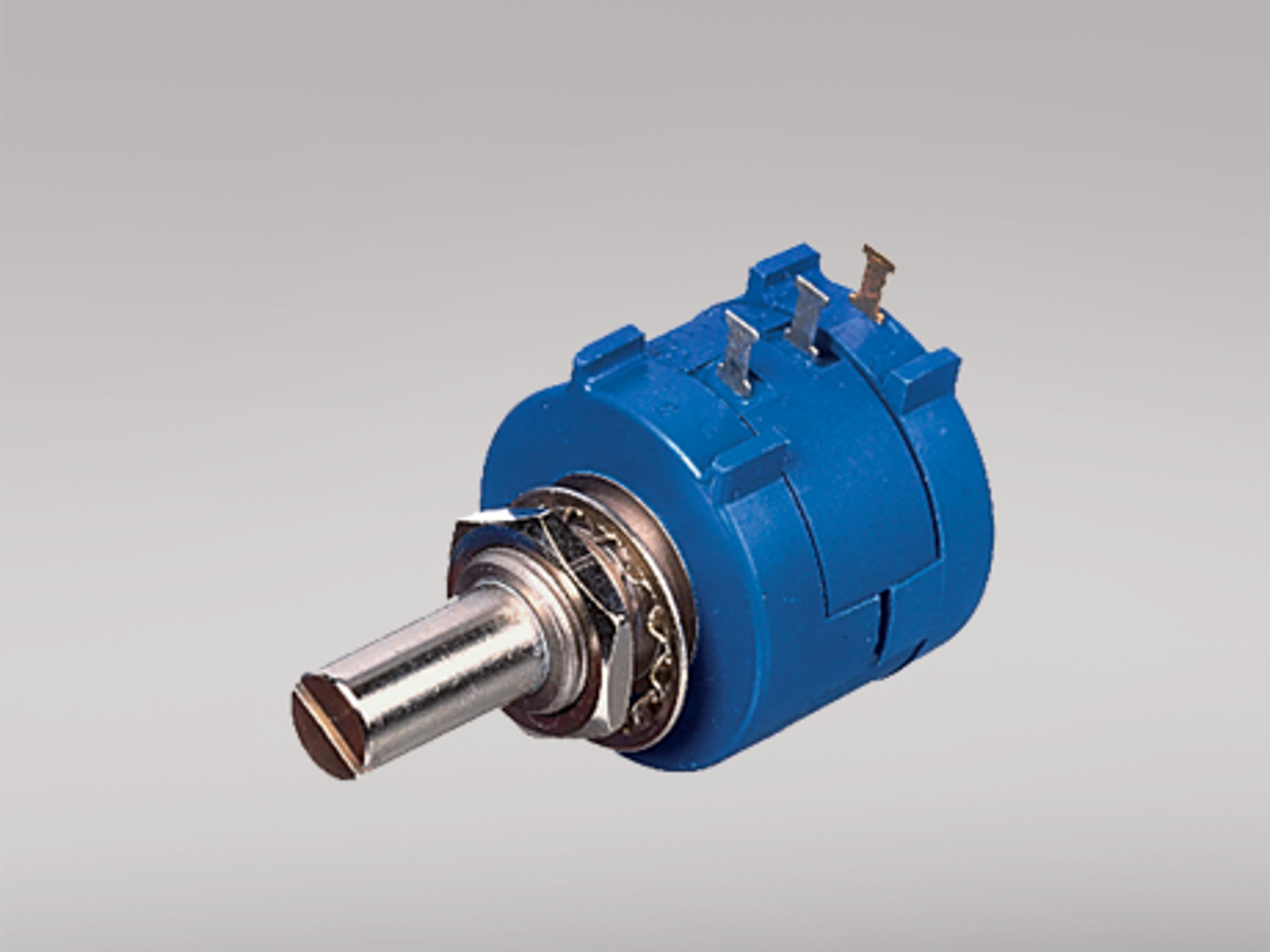
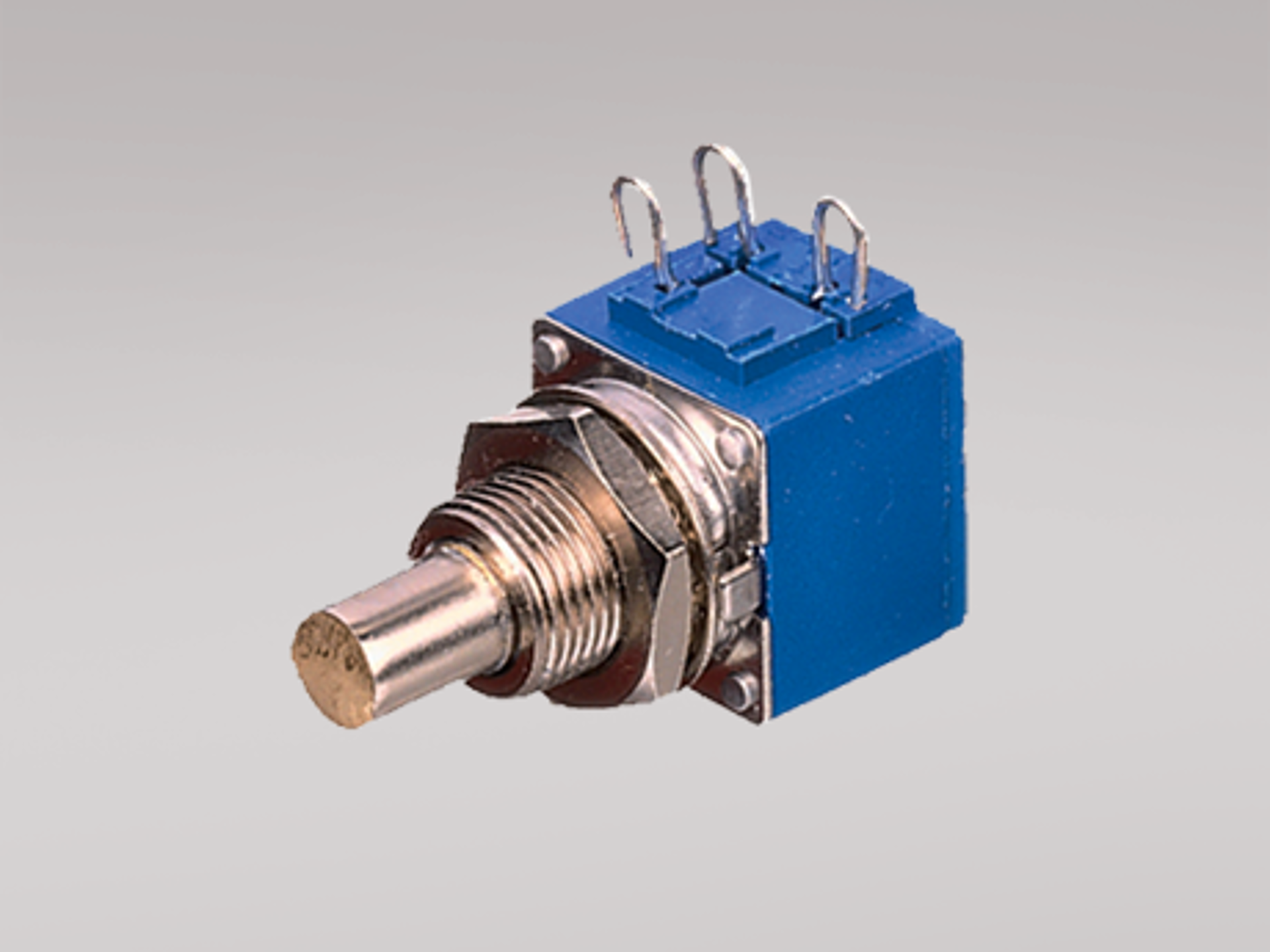
- Input for RTD, TC, Ohm, potentiometer, mA and V
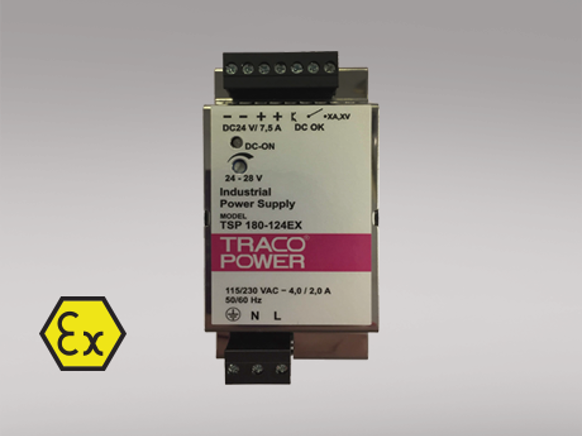
- Supply for 2-wire transmitters
- Active / passive mA output and relay output
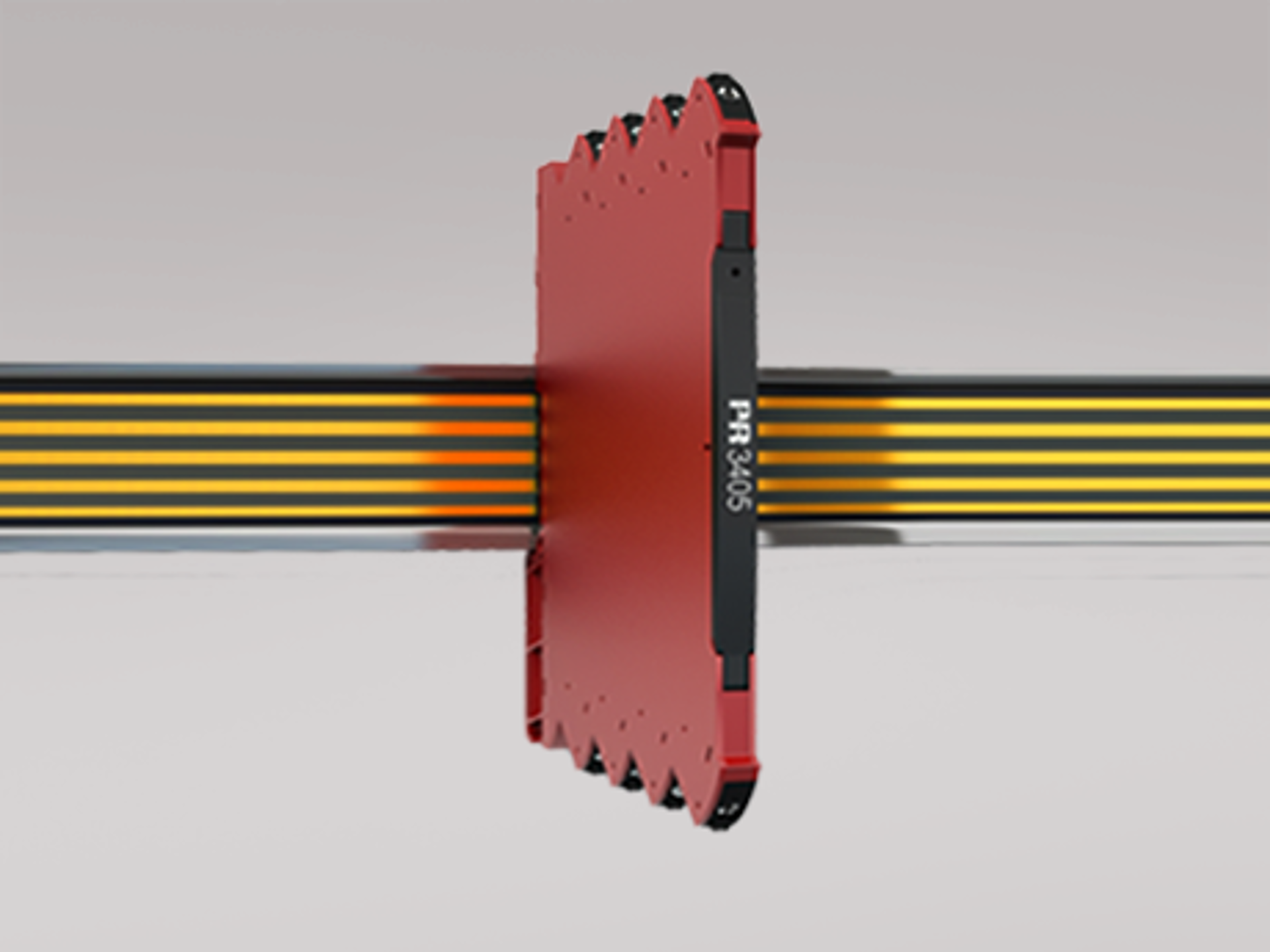
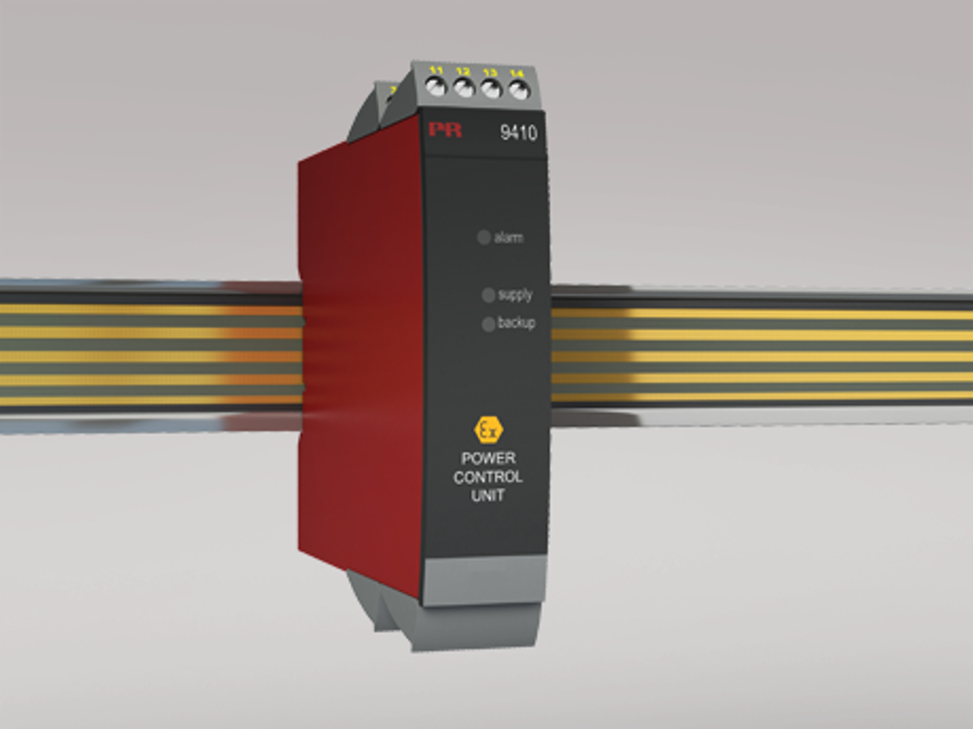
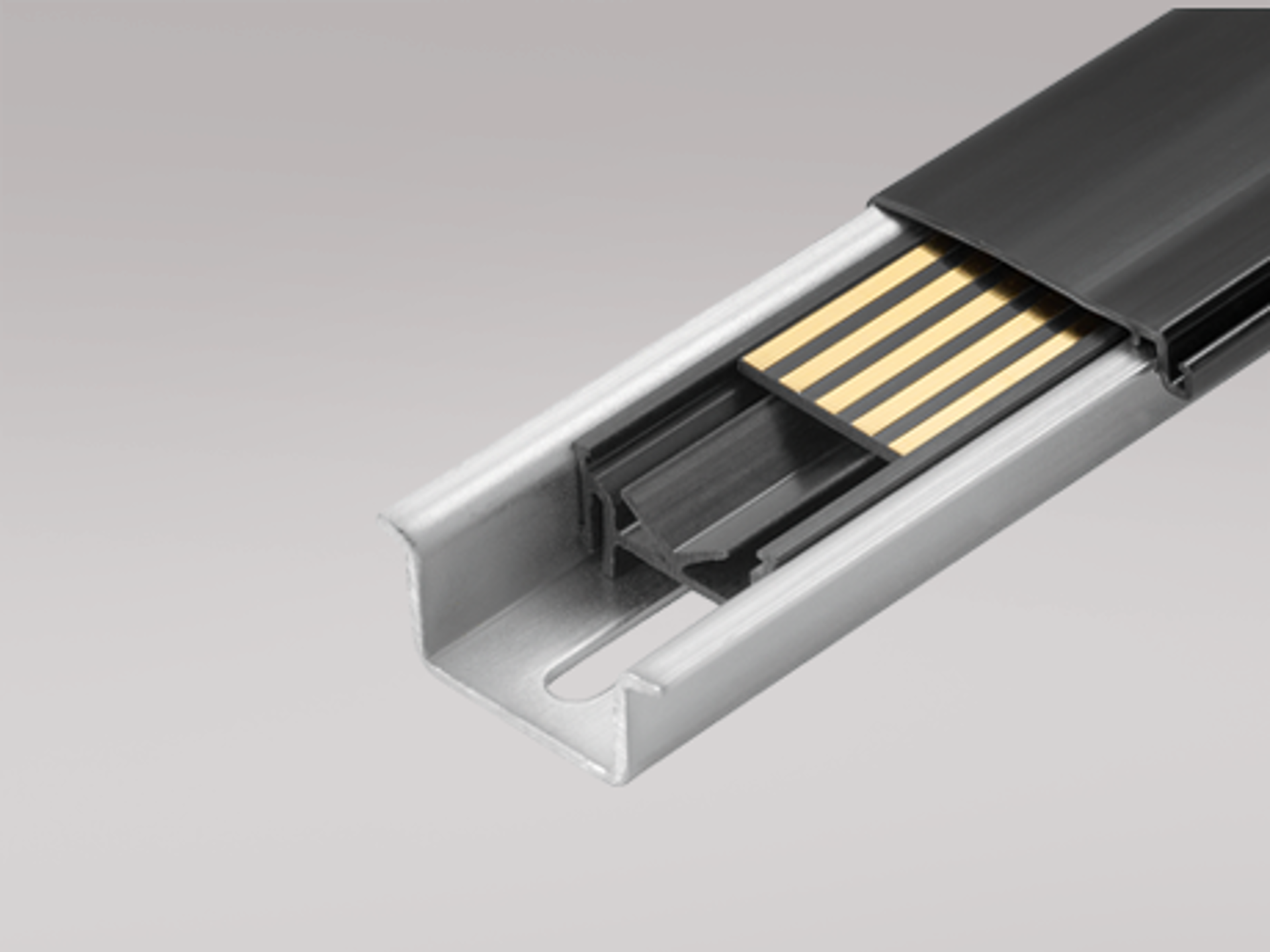
- Can be supplied separately or installed on power rail, PR type 9400
- SIL 2-certified via Full Assessment
Advanced features
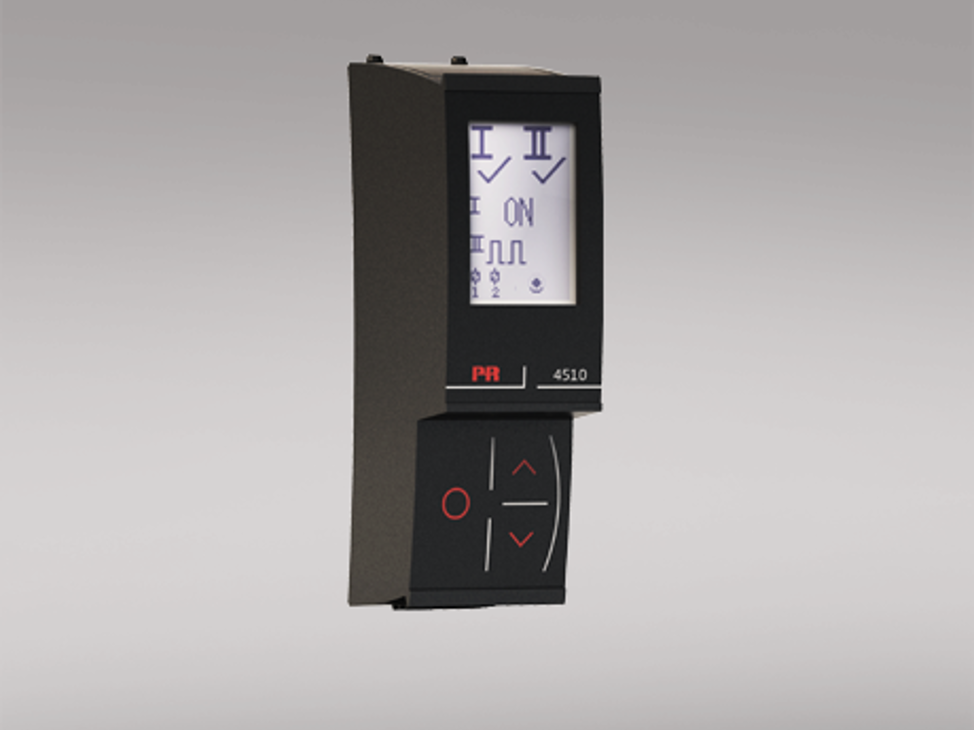
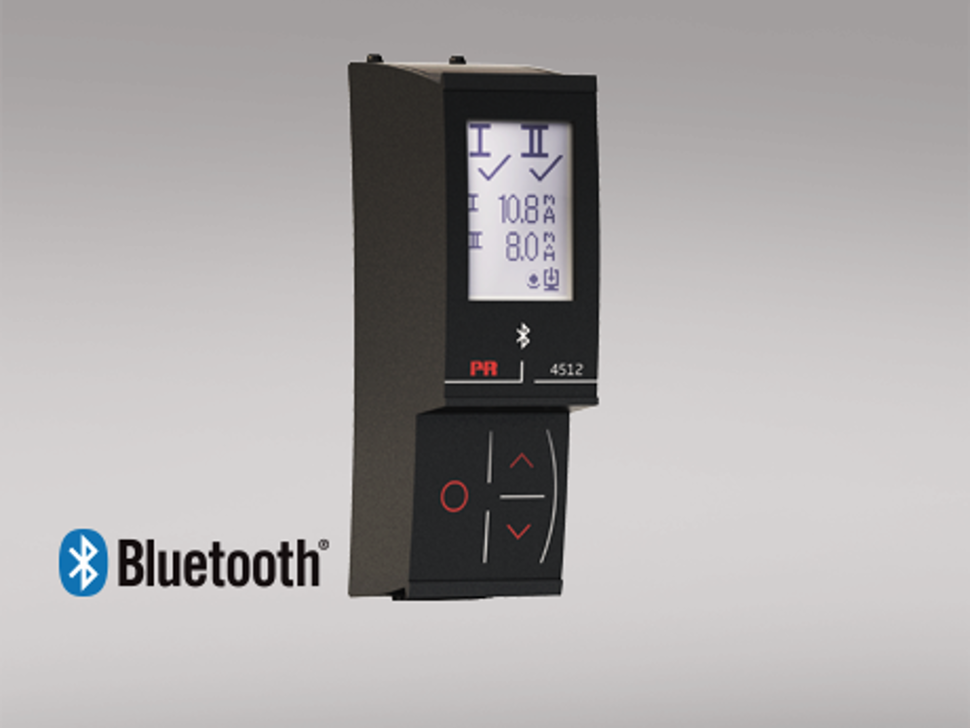
- Configuration and monitoring by way of detachable display front (PR 4500 series); process calibration, signal and relay simulation.
- Advanced relay configuration, e.g. setpoint, window, delay, sensor error indication and power monitoring.
- Copying of the configuration from one device to others of the same type via the display front.
- TC inputs with internal CJC or external CJC for higher accuracy.
- Active / passive mA output via the same two terminals.
Application
- 9116A can be mounted in the safe area or in zone 2 / Class I, Division 2, Groups A, B, C, D.
- Conversion and scaling of temperature, voltage, potentiometer and linear resistance signals.
- Power supply and signal isolator for 2-wire transmitters.
- Monitoring of error events and cable breakage via the individual status relay and/or a collective electronic signal via the power rail.
- 9116A has been designed, developed and certified for use in SIL 2 applications according to the requirements of IEC 61508.
- Suitable for the use in systems up to Performance Level “d” according to ISO-13849.
Technical characteristics
- 1 green and 1 red front LED indicate operation status and malfunction. 1 yellow LED indicates relay status.
- 2.6 kVAC galvanic isolation between input, output and supply.
Mounting
- The devices can be mounted vertically or horizontally without distance between neighbouring units.
Data sheet & Manuals
Safety note
Safety note
Approvals & Certificates
FM certificate
- 9116_FM19US0058X_FM19CA0031X.pdf
- Latest version
INMETRO certificate
- 9116_INMETRO_230006X_issue0.pdf
- Latest version
CCC certificate
- 9116_CCC_2024_05.pdf
- Latest version
KCs certificate
- 9116A_KCs_21_AV4BO_0178X.pdf
- Latest version
UL certificate
SIL certificate
- 9116_003_SIL.pdf
- Latest version
DNV marine certificate
- DNV_9xxx_4510_4511.pdf
- 9000_DoC_DNV.pdf
- Previous versions
- Latest version
ClassNK certificate
- ClassNK-TA24034M_91xx_92xx_94xx.pdf
- Latest version
EAC declaration
- EAC_EMC_declaration_Ex_3000_5000_6000_9000.pdf
- Latest version
EAC LVD declaration
- EAC_LVD-Declaration.pdf
- Latest version
EAC Ex certificate
- EAC_Ex.pdf
- Latest version
Metrology Pattern Approval (MPA), Russia
- MPA_Russia.pdf
- Latest version
Supplementary documentation
Modbus configuration manual
- 9116_MCM_101.pdf
- 9116_MCM_100.pdf
- Previous versions
- Latest version
EMC data
- 9000_EMC_data.pdf
- Latest version
Assessment report
- AssessmentReport_PR_2312098_V1R0_Series_9000.pdf
- Latest version
FMEDA report
- PR_060319_R024_FMEDA_9116_V3R4.pdf
- Latest version
PR default configurations
- PR_default_configurations.pdf
- Latest version
Order form
Environmental Conditions
| Operating temperature | -20°C to +60°C |
| Storage temperature | -20°C to +85°C |
| Calibration temperature | 20...28°C |
| Relative humidity | < 95% RH (non-cond.) |
| Protection degree | IP20 |
| Installation in | Pollution degree 2 & meas. / overvoltage cat. II |
Mechanical specifications
| Dimensions (HxWxD) | 109 x 23.5 x 104 mm |
| Dimensions (HxWxD) w/ PR 4500 | 109 x 23.5 x 131 mm |
| Weight approx. | 185 g |
| DIN rail type | DIN EN 60715/35 mm |
| Wire size | 0.13...2.08 mm2 AWG 26...14 stranded wire |
| Stripping length | 5 mm |
| Screw terminal torque | 0.5 Nm |
| Vibration | IEC 60068-2-6 |
| 2...13.2 Hz | ±1 mm |
| 13.2...100 Hz | ±0.7 g |
Common specifications
Supply |
|
| Supply voltage | 19.2...31.2 VDC |
| Fuse | 1.25 A SB / 250 VAC |
| Max. required power | ≤ 2.1 W |
| Max. power dissipation | ≤ 1.7 W |
Isolation voltage |
|
| Test /working: Input to any | 2.6 kVAC / 300 VAC reinforced isolation |
| Analog output to supply | 2.6 kVAC / 300 VAC reinforced isolation |
| Status relay to supply | 1.5 kVAC / 150 VAC reinforced isolation |
Response time |
|
| Temperature input, programmable (0...90%, 100...10%) | 1...60 s |
| mA / V input (programmable) | 0.4...60 s |
Auxiliary supplies |
|
| 9116x1x: 2-w. sup. (term. 54...52) | 28...16.5 VDC / 0...20 mA |
| 9116x2x: 2-w. sup. (term. 54...52) | 21.4...16.5 VDC / 0...20 mA |
| Programming | PR 4500 communication interfaces |
| Signal dynamics, input | 24 bit |
| Signal dynamics, output | 16 bit |
| Signal / noise ratio | Min. 60 dB (0...100 kHz) |
| Accuracy | Better than 0.1% of sel. range |
Input specifications
RTD input |
|
| RTD type | Pt10/20/50/100/200/250; Pt300/Pt400/500/1000; Ni50/100/120/1000 |
| Cable resistance per wire | 50 Ω (max.) |
| Sensor current | Nom. 0.2 mA |
| Effect of sensor cable resistance (3-/4-wire) | < 0.002 Ω / Ω |
| Sensor error detection | Programmable ON / OFF |
| Short circuit detection | Yes |
Potentiometer input |
|
| Potentiometer min....max. | 10 Ω...10 kΩ |
TC input |
|
| Thermocouple type | B, E, J, K, L, N, R, S, T, U, W3, W5, LR |
| Cold junction compensation (CJC) via ext. sensor in 5910 | 20...28°C ≤ ±1°C, -20...20°C / 28...70°C ≤ 2°C |
| CJC via int. mounted sensor | ±(2.0°C + 0.4°C * Δt) |
| Sensor error detection | Programmable ON or OFF (only wire breakage) |
Current input |
|
| Measurement range | 0...23 mA |
| Programmable measurement ranges | 0...20 and 4...20 mA |
| Input resistance | Nom. 20 Ω + PTC 50 Ω |
| Sensor error detection | Loop break 4...20 mA |
Voltage input |
|
| Measurement range | 0...12 VDC |
| Programmable measurement ranges | 0/0.2...1, 0/1...5, 0/2...10 VDC |
| Input resistance | Nom. >10 MΩ |
Output specifications
Current output |
|
| Signal range | 0...23 mA |
| Programmable signal ranges | 0...20/4...20/20...0/20...4 mA |
| Load (@ current output) | ≤ 600 Ω |
| Load stability | ≤ 0.01% of span / 100 Ω |
| Sensor error indication | 0 / 3.5 / 23 mA / none |
| NAMUR NE43 Upscale/Downscale | 23 mA / 3.5 mA |
| Current limit | ≤ 28 mA |
Passive 2-wire mA output |
|
| Max. external 2-wire supply | 26 VDC |
| Effect of external 2-wire supply voltage variation | < 0.005% of span / V |
Relay output |
|
| Relay functions | Setpoint, Window, Sensor error, Power and Off |
| Max. voltage | 250 VAC / VDC |
| Max. current | 2 A |
| Max. AC power | 500 VA |
| Max. DC current, resistive load > 30 VDC | See manual for details |
Status relay |
|
| Max. voltage | 125 VAC / 110 VDC |
| Max. current | 0.5 AAC / 0.3 ADC |
| Max. AC power | 62.5 VA / 32 W |
Observed authority requirements
| EMC | 2014/30/EU & UK SI 2016/1091 |
| LVD | 2014/35/EU & UK SI 2016/1101 |
| RoHS | 2011/65/EU & UK SI 2012/3032 |
| ATEX | 2014/34/EU & UK SI 2016/1107 |
| EAC | TR-CU 020/2011 |
| EAC Ex | TR-CU 012/2011 |
| EAC LVD | TR-CU 004/2011 |
Approvals
| ATEX | KEMA 10ATEX0053 X |
| IECEx | KEM 10.0022X |
| UKEX | DEKRA 21UKEX0177X |
| c FM us | FM19US0058X / FM19CA0031X |
| INMETRO | DEKRA 23.0006X |
| c UL us, UL 61010-1 | E314307 |
| c UL us, UL 913 | E233311 (only 9116xx-U9) |
| CCC | 2024322316005917 |
| KCs | 21_AV4BO_0178X (only 9116Ax-KCs) |
| EAC Ex | EAEU KZ 7500361.01.01.08756 |
| DNV Marine | TAA00000JD |
| ClassNK | TA24034M |
| SIL | SIL 2 certified & fully assessed acc. to IEC 61508 |


Need support to select the right product for your application?
Our sales engineers are ready to help specify the right device to meet your needs.
Reach out by phone to get in touch with us straight away – or use the contact form or quick quote function to send your RFQ directly from the website. You’ll get a response within 24 hours on normal business days.
You can expect to get a confirmed delivery date via email within 2 days after we have received your order.
As soon as your package leaves our warehouse, you’ll receive tracking details via email. And if you have any questions along the way we’re just a phone call or email away.
 |
State-of-the-art manufacturing Our 8,500 sqm integrated and automated manufacturing campus in Denmark covers the entire value-chain from design and development to manufacturing. It allows us to design and optimize for testing and manufacturing thereby constantly driving quality up and costs down. |
 |
Dedicated Presale / Aftersales
|
 |
Product reliability |
 |
Product deployment
|
 |
Smart products
Check out our range of communication interfaces
|
