



10 practical ways to protect process signals from electrical noise
Electromagnetic interference, or EMI, is commonly found in industrial environments and can adversely affect the accuracy of your instrumentation signals.
Electrical noise is one of the most common causes of unstable readings in industrial plants. Frequency drives, motors, contactors and handheld radios all generate electromagnetic interference (EMI) that can couple into signal cables and show up as jumping values, offsets or unexplained trips.
Most EMI problems can be prevented through a few deliberate design and installation choices. The ten tips below are grouped into three areas – cabling, shielding and grounding, and signal and equipment choice. Each tip briefly explains why it works, so you can apply the principle to your own installation.
Cabling
1. Signal and power cable spacing
Route instrumentation cables in separate trays or conduits from power and motor cables. Coupling between cables decreases with distance and increases with the length over which they run in parallel – so both matter.
A separation of 10 centimeters or more is a common rule of thumb, and drive manufacturers typically specify a minimum distance for motor cables in their installation manuals. If a shared tray cannot be avoided, use a grounded metal divider.
Where signal and power cables have to cross, cross them at 90°. At right angles, the magnetic field from the power cable couples very little into the signal cable. Electrical coupling is also reduced because the length over which the cables run close to each other is minimized.
2. Keep signal and return conductors together
A magnetic field induces a voltage in the loop formed by a signal conductor and its return path – and the larger the loop area, the larger the induced voltage.
Run the signal and its return in the same cable, keep the pair together all the way to the terminals, and never route them along different paths.
Avoid leaving excess cable coiled next to noise sources such as drives or transformers, as the coil of cable will act as an antenna, picking up noise from the surroundings.
3. Use twisted pairs – and know what the shield does
Twisting reduces magnetic coupling because the voltages induced in successive twists have opposite polarity and largely cancel out. The shield does a different job: it mainly protects against electric-field (capacitive) coupling and high-frequency interference.
A thin foil shield offers little protection against low-frequency magnetic fields, such as 50/60 Hz fields from nearby power cables – that is what twisting and distance are for. In noisy environments, use cables that are both twisted and shielded.
Shielding and grounding
4. Terminate shields with a 360° connection
A shield is only as good as its termination. A long “pigtail” – the shield braid twisted into a wire and connected to a terminal – adds inductance and can make the shield almost ineffective at high frequencies.
Connect the shield all the way around the cable using a shield clamp or EMC cable gland, and do it where the cable enters the cabinet, so interference is diverted to ground before it gets inside.
5. Choose a grounding strategy – and apply it consistently
Grounding the shield at both ends gives the best protection against high-frequency interference. But if the ground potential differs between the two ends, a low-frequency current will flow in the shield.
Grounding at one end only (typically the control-room end) avoids this current but gives less high-frequency protection.
The right choice depends on the plant’s equipotential bonding: with a well-meshed bonding network, grounding at both ends is generally preferred; without it, single-end grounding is the traditional choice in process instrumentation.
Whatever you choose, apply the principle consistently across the installation. In hazardous areas, intrinsically safe circuits have specific shield earthing requirements (IEC 60079-14) that must be followed.
6. Deal with the noise at the source
Frequency drives are the most common source of interference in modern plants. Use shielded, symmetrical motor cables with 360° shield connections at both the drive and the motor, keep the drive’s input filter in place, and consider output (du/dt or sine-wave) filters on long motor cables.
Inside the cabinet, separate “noisy” zones (drives, contactors, switched-mode power supplies) from “clean” zones with instrumentation and signal conditioning.
Signal and equipment choice
7. Convert low-level signals close to the sensor
Thermocouple signals are in the range of tens of microvolts per degree. For a type K thermocouple, just 1 mV of picked-up noise corresponds to an error of roughly 24 °C. Sending such a signal through a long cable in a noisy plant is asking for trouble.
Mounting a transmitter in the sensor head – or close to the measuring point – converts the signal to 4–20 mA over the shortest possible distance.
A current signal is far more robust: the current is not affected by cable resistance, and the low-impedance loop is much less susceptible to induced interference than a high-impedance millivolt signal.
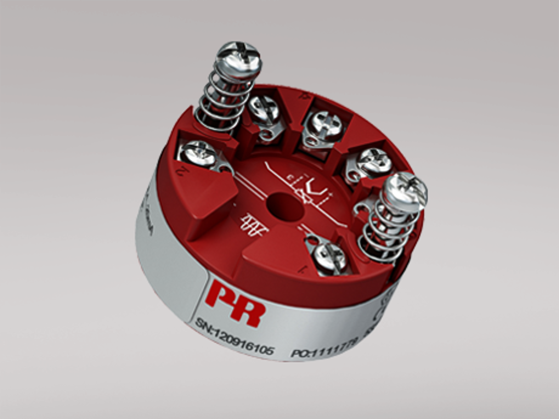
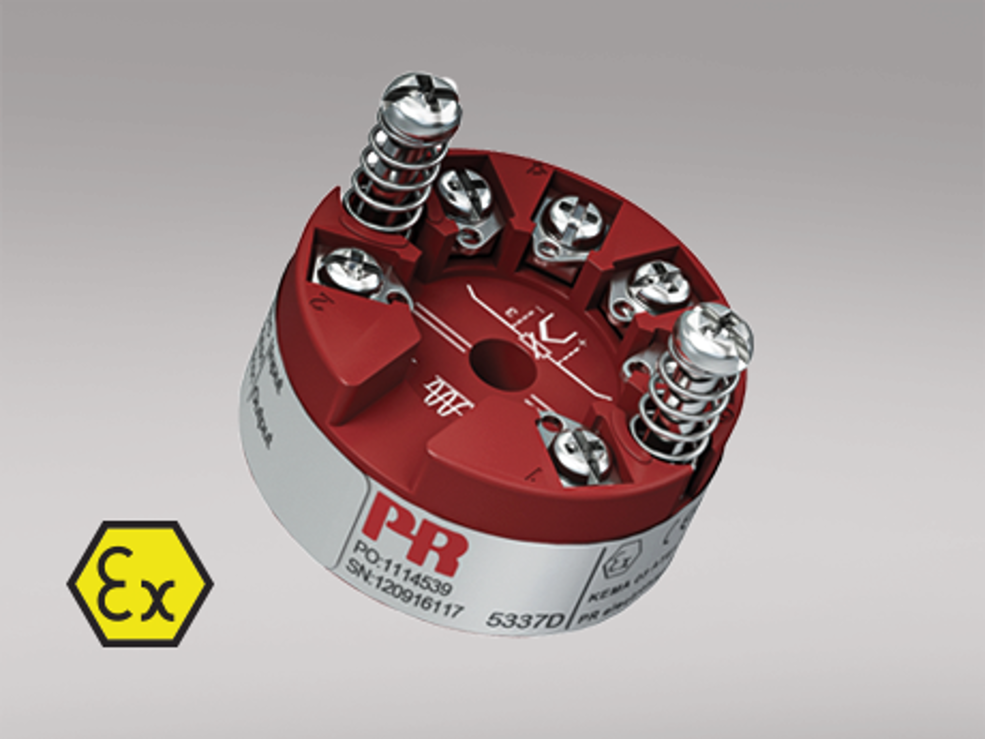
How PR electronics can help: PR electronics head-mounted temperature transmitters convert RTD, thermocouple and mV signals to 4–20 mA right at the measuring point – with galvanic isolation between input and output (2.5 kVAC on the PR 5437). Explore head-mounted temperature transmitters. |
8. Break ground loops with galvanic isolation
When a measurement loop is grounded at more than one point, differences in ground potential can drive current through the signal wiring and show up as offsets or noise. Grounded-junction thermocouples, where the measuring junction is in contact with a grounded thermowell, are a classic example.
Galvanic isolation breaks this path: input, output and supply are electrically separated while the measurement signal is transferred across the barrier. But not all isolation is equal.
Fast common-mode transients can still couple across the barrier’s internal capacitance, so the isolator’s own EMC (electromagnetic compatibility) immunity matters as much as its isolation voltage. If the loop carries HART communication, choose an isolator that is HART-transparent.
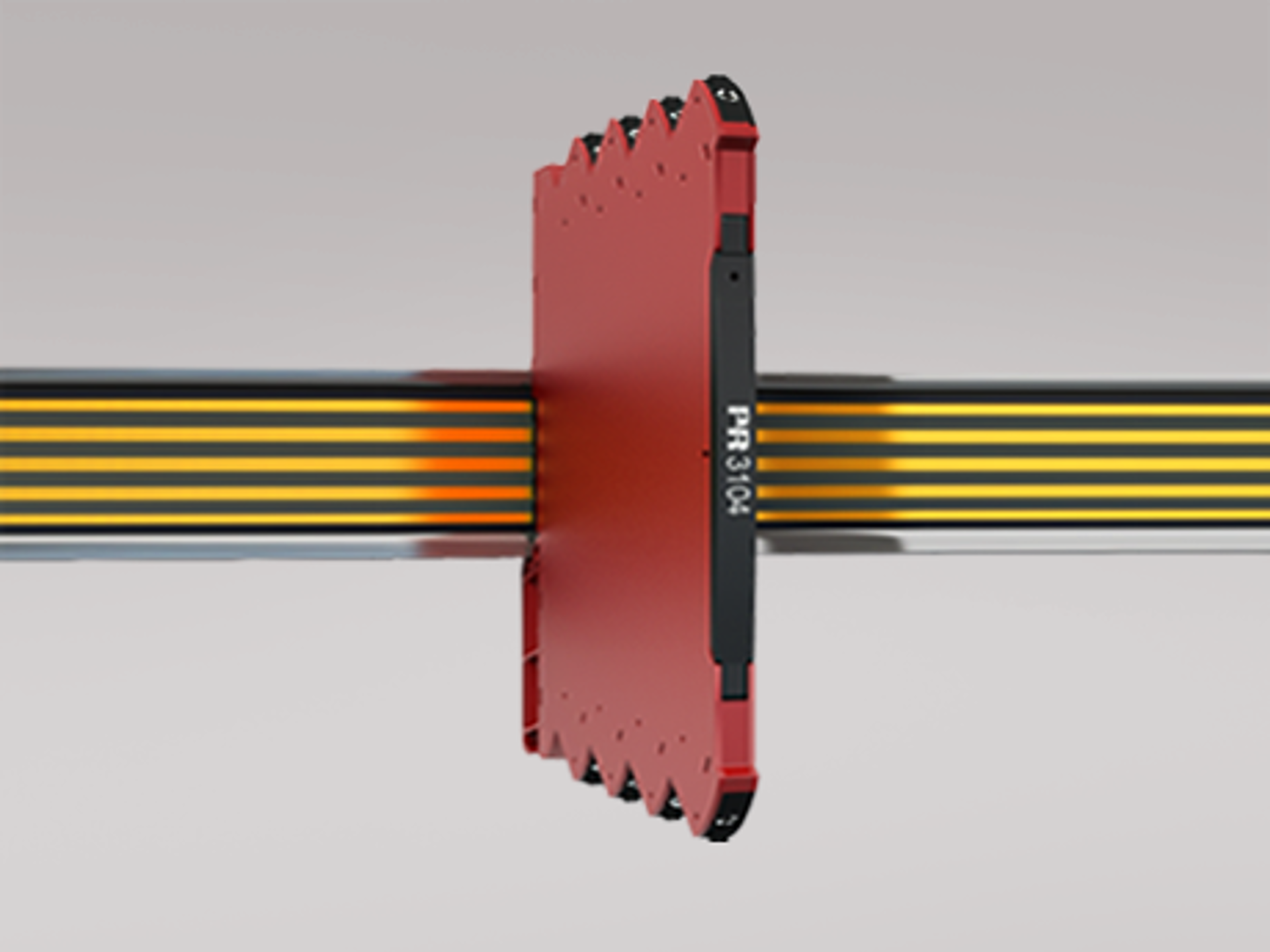
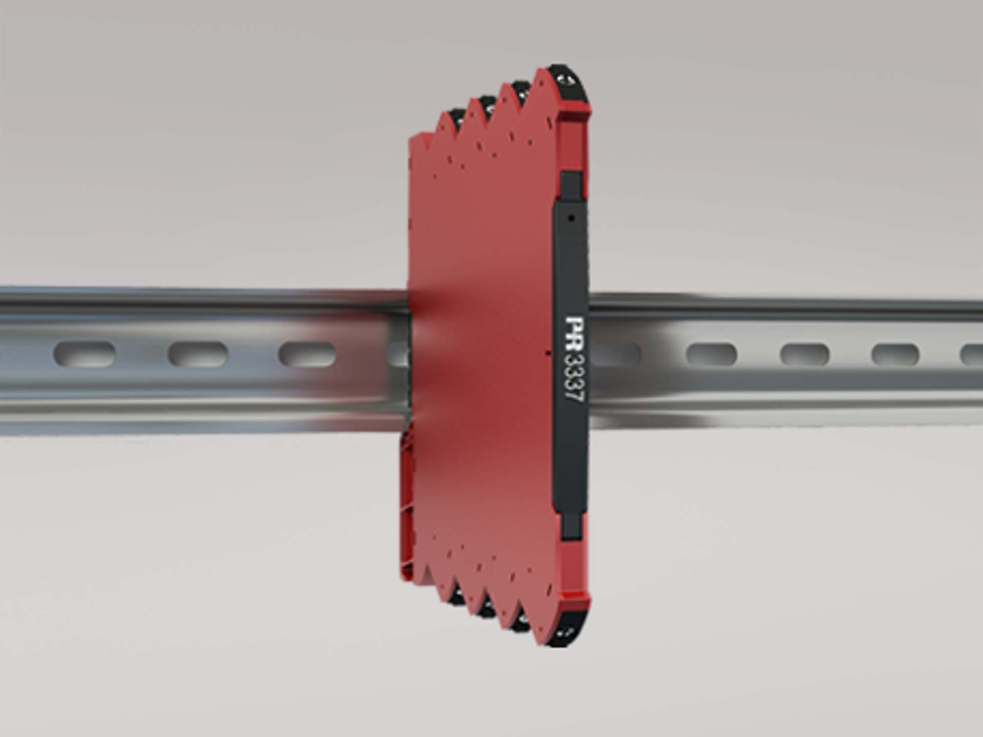
How PR electronics can help: Galvanic isolation is at the core of PR’s signal conditioning portfolio – from slim DIN-rail isolators to universal converters and HART-transparent repeaters for hazardous areas. Explore signal isolators. |
9. Choose equipment with documented EMC (electromagnetic compatibility) immunity
CE marking shows that a product meets the minimum requirements – not how well it performs in your plant. Check the datasheet: the EMC immunity influence tells you how much the measurement may deviate during testing.
NAMUR NE 21, widely used in the process industry, adds requirements beyond those of the basic standard IEC 61326-1, and IEC 61326-3-1 applies to equipment performing safety functions.
Real plants are often tougher than the test lab. A handheld radio held close to a cabinet can easily exceed the 10 V/m field strength used for industrial immunity testing.
How PR electronics can help: PR electronics products are designed to exceed standard EMC requirements, and our datasheets state the EMC immunity influence – for example, less than ±0.5% of span under standard EMC testing and less than ±1% of span under NAMUR NE 21 extended testing for the PR 3103 isolator. |
10. Use filtering as a last resort – not a first fix
Most transmitters and control systems let you add damping or increase the response time to smooth out a noisy signal.
It can be useful, but it hides the symptom rather than removing the cause – and it slows down the measurement, which can affect control performance and safety functions. Find and fix the source first; use filtering to fine-tune.
Robust measurements are designed – not added afterward
There is rarely one single measure that eliminates EMI. Cable routing, shielding, grounding, signal type, and equipment choice all interact, and a weakness in one area can undo the effort in the others.
Use the ten tips as a checklist when designing new installations – and as a starting point when troubleshooting existing ones. A good first question: does the noise appear when a specific drive, pump or radio is in use?
At PR electronics, EMC performance is built into our products from the first design phase – because a signal conditioner is only as good as the signal it delivers in a real plant.
Want to go deeper? Join our upcoming webinar
Join our webinar on electromagnetic interference with our own EMC specialist, Michael Breer, on October 22, 2026 to learn how interference couples into instrumentation signals, how to identify the source, and what to consider when designing robust measurement systems.
Sign up for the EMI webinar
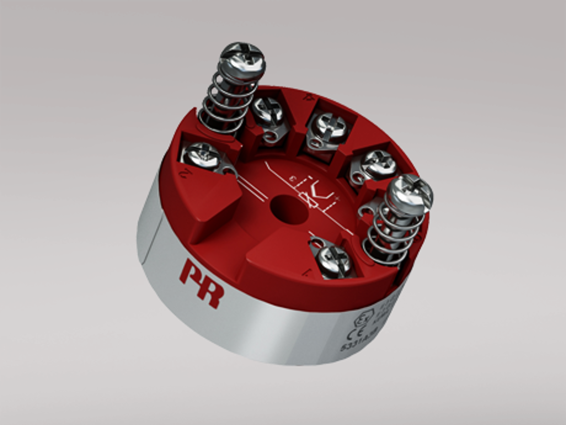
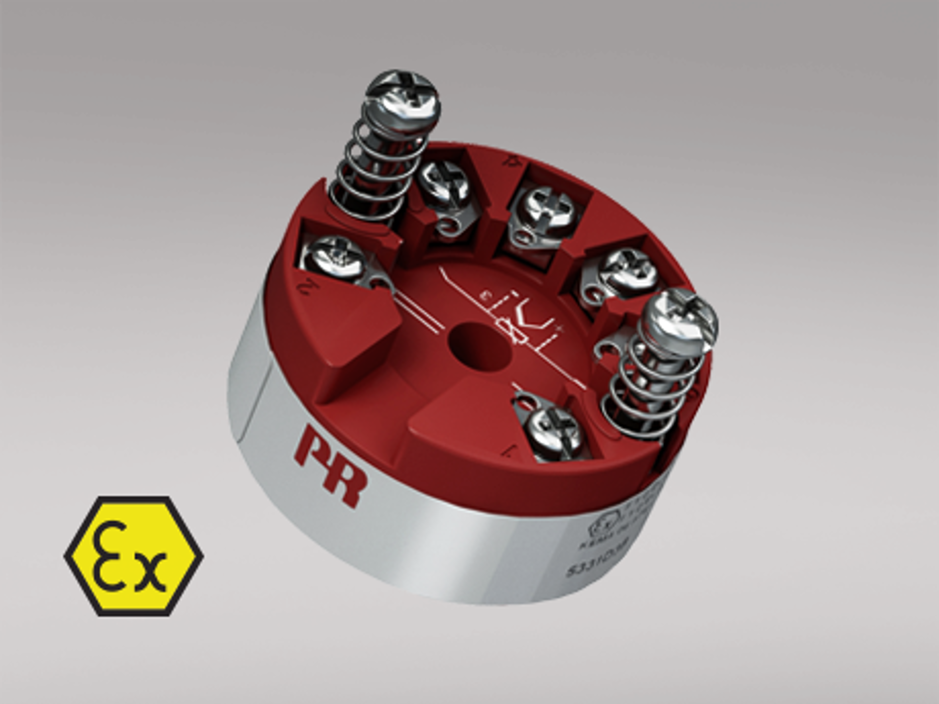
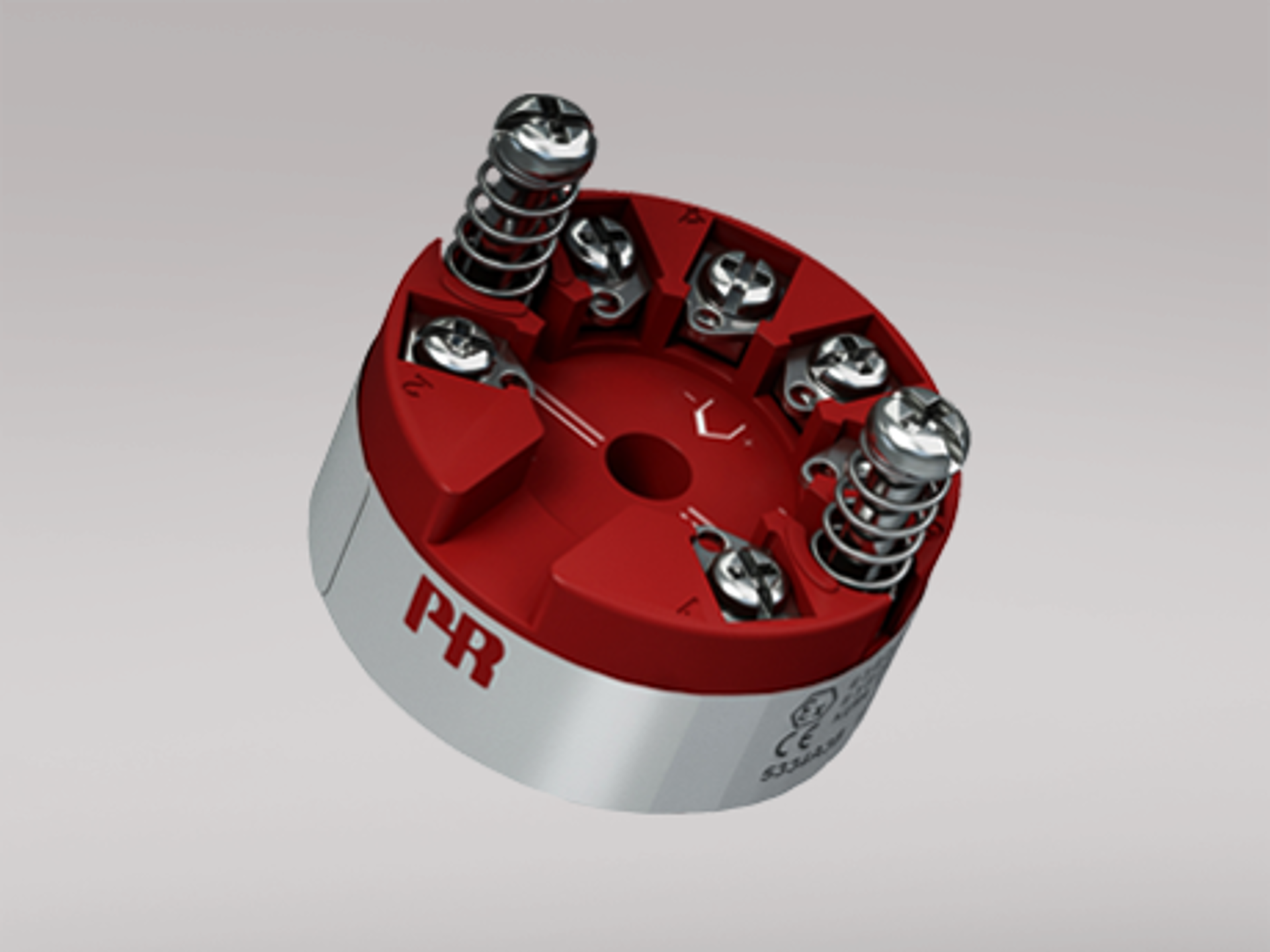
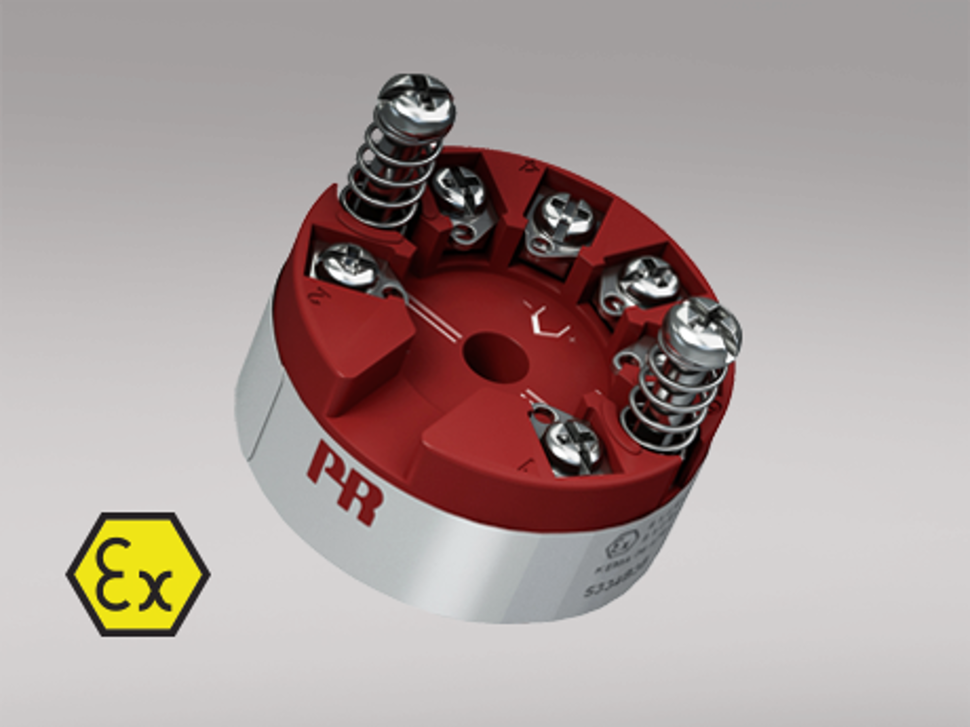
Examples of isolated head mounted temperature transmitters:
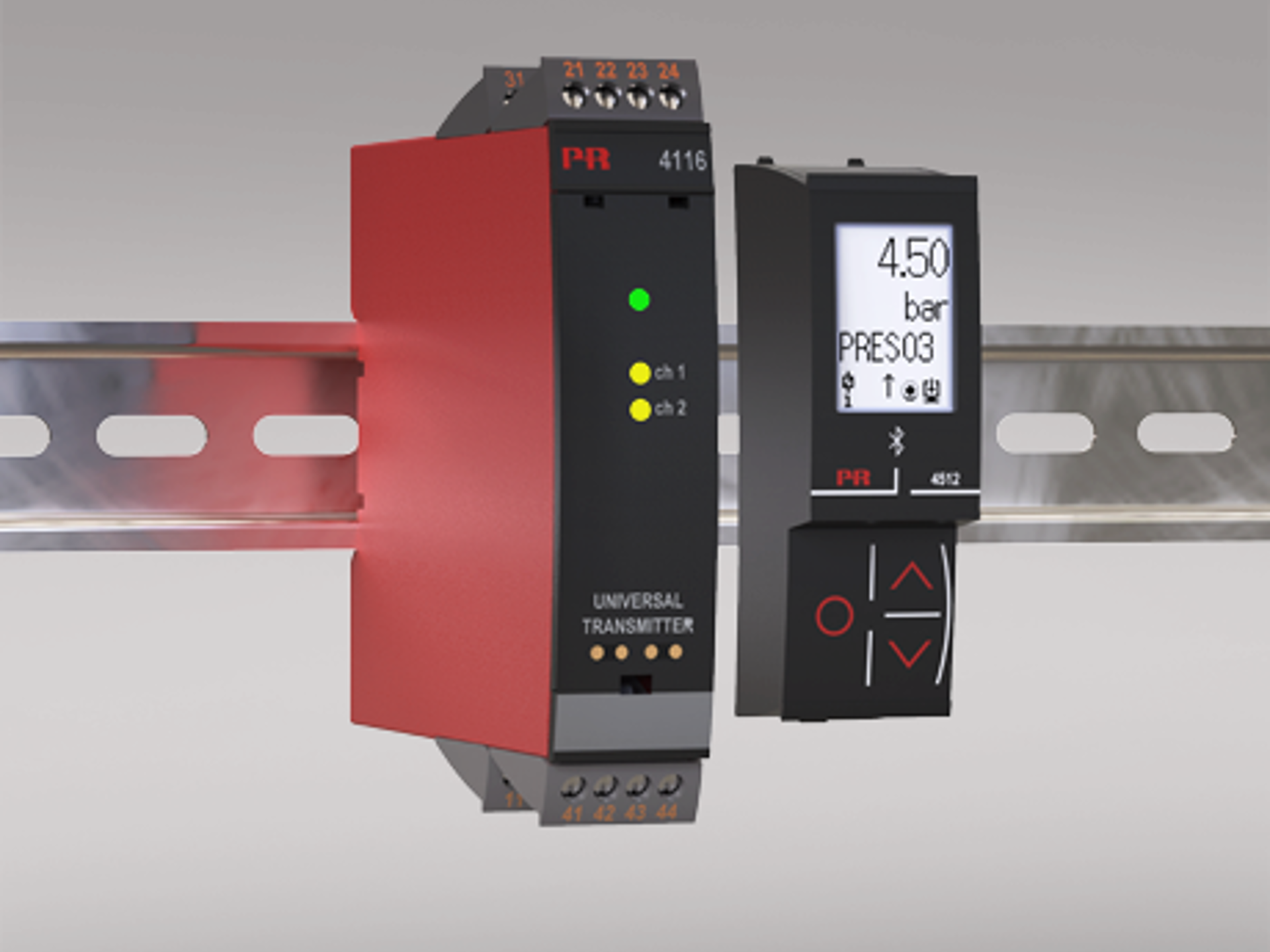
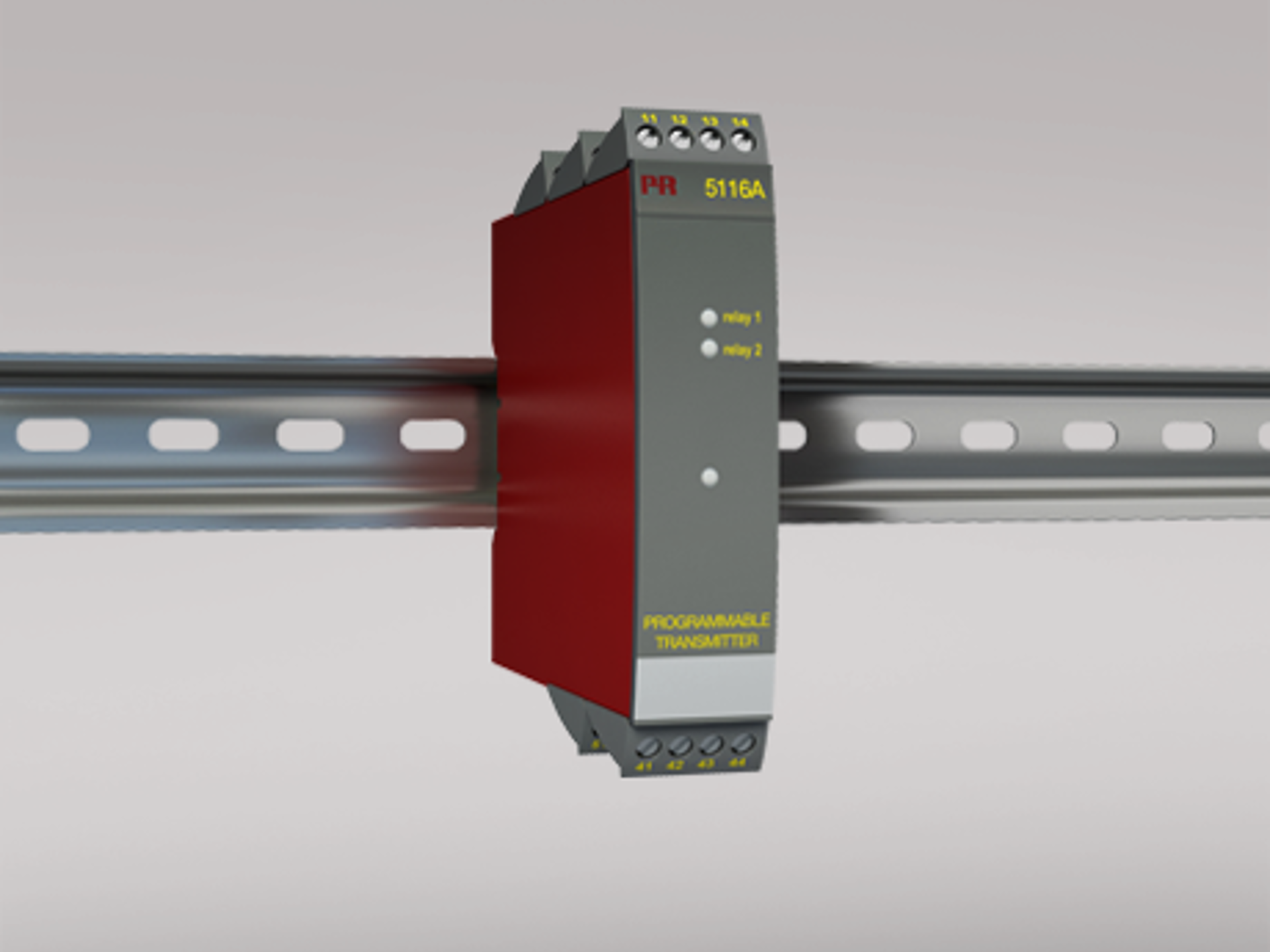
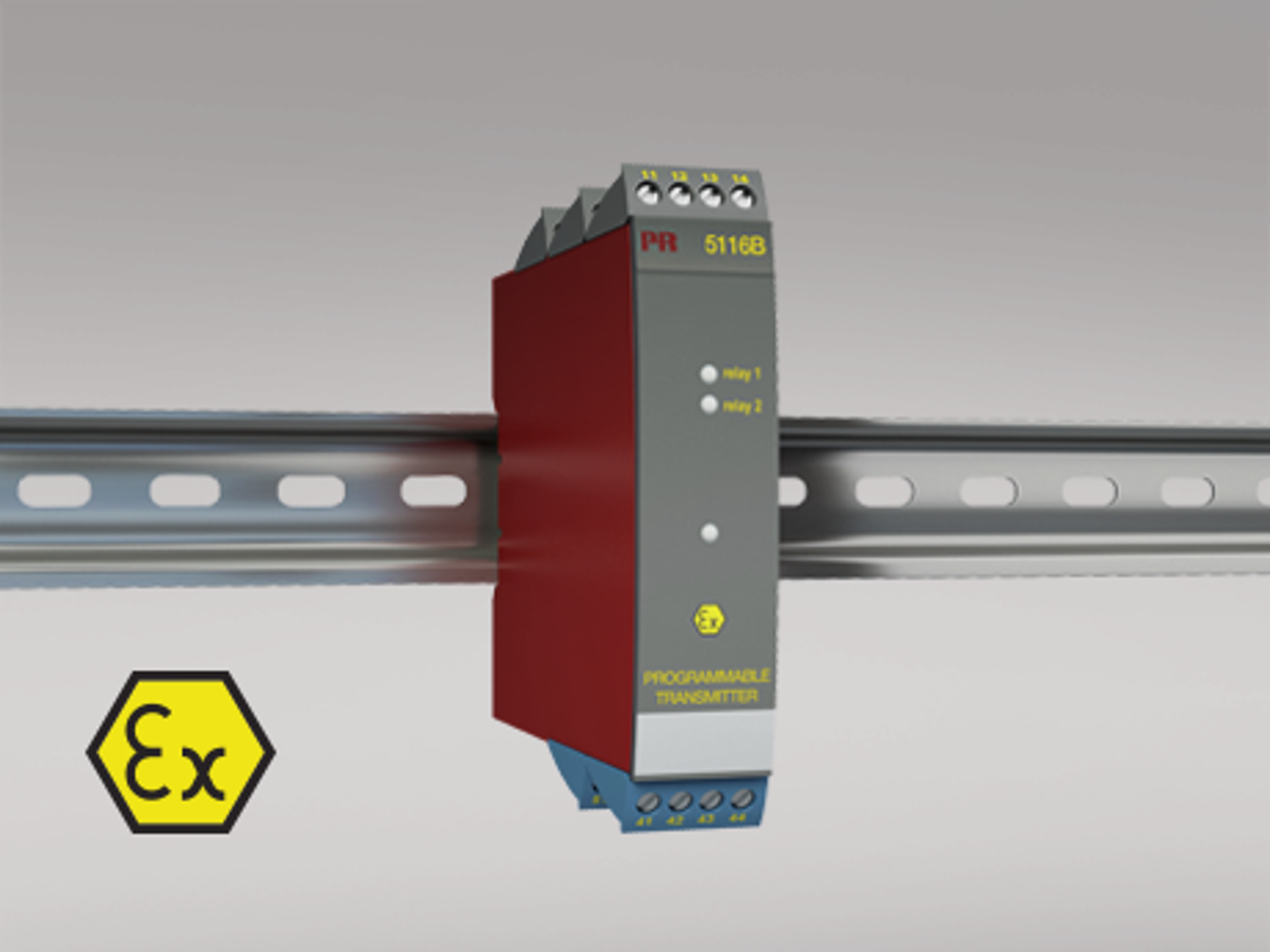
Examples of isolated DIN rail mounted transmitters:
What is EMI?
EMI refers to the term Electromagnetic Interference. Electromagnetic interference from natural phenomena such as lightning or from one electronic device to another through conduction or radiation. EMI can affect the normal operation of electrical devices and should be minimized.
What does EMI stand for?
EMI refers to the term Electromagnetic Interference
What does EMI mean?
EMI refers to the term Electromagnetic Interference
What is EMI in electronics?
This refers to conducted or radiated electromagnetic interference experienced or generated by electronic circuitry or devices whilst in operation
What is EMI filter?
An EMI filter is a device used to reduce typically conducted electromagnetic interference. This is achieved by suppressing high frequency transients in power and signal lines.
What is EMI shielding?
EMI shielding is used to protect circuitry and cabling from radiated elecromagnetic interference. Shielding is normally a formed metallic screen designed to absorb EMI and to prevent it affecting sensitive signals or electronics.